40
Module Settings
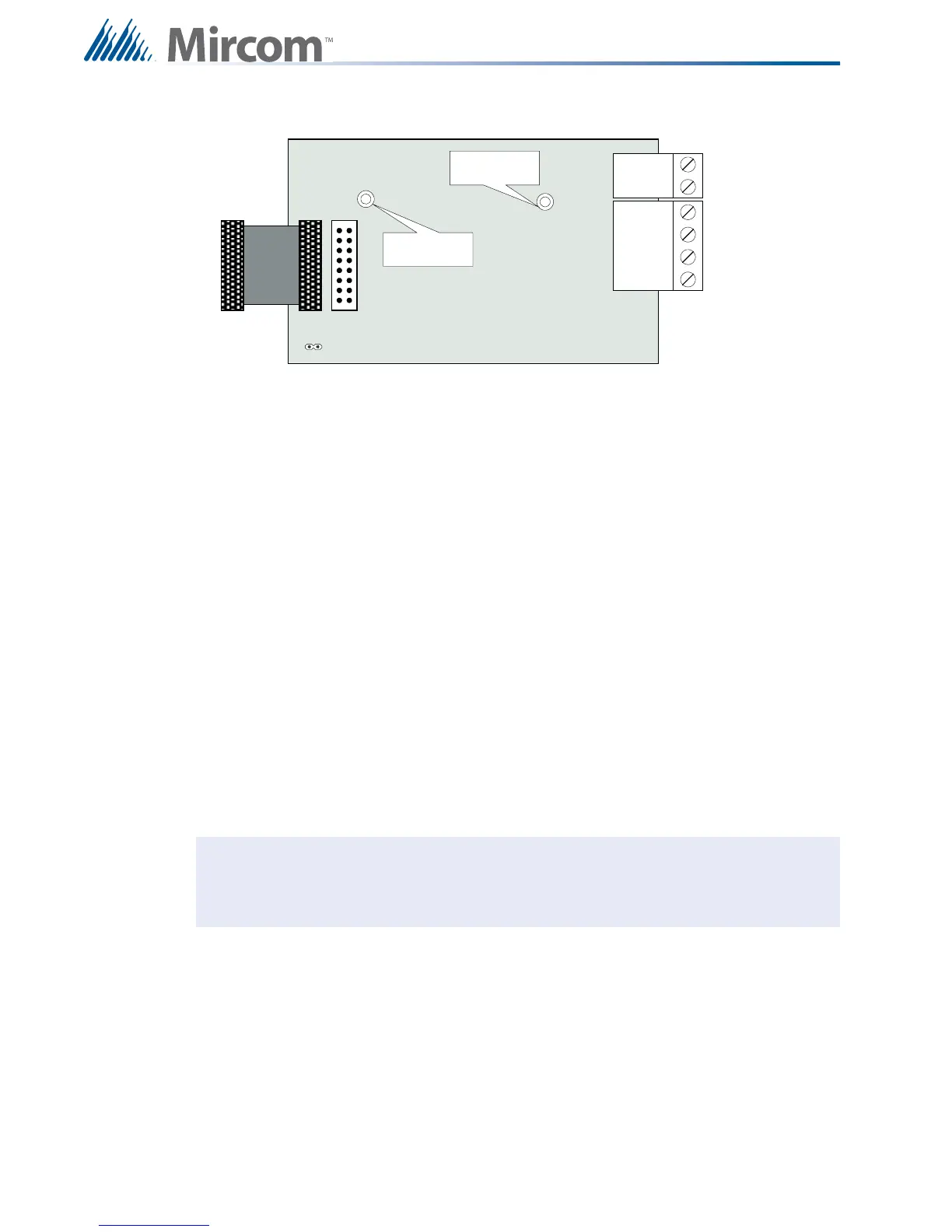
7.9 Polarity Reversal and City Tie Module (Model PR-300)
Figure 26 Polarity reversal and city tie module
The following hardware configuration must be performed before installing the PR-300.
Table 9 PR-300 jumper settings
The Alarm Transmit signal to the PR-300 can be programmed to turn OFF when signal silence
is active. This allows the City Tie Box to be manually reset. On subsequent alarms the
silenceable signals will resound and the City Tie Box will be retriggered. Please refer to the
Configurator for more information.
The Trouble Transmit signal to the PR-300 can be programmed to delay AC power fail. Please
refer to the Configurator for more information.
P1 Cable connects to P5 on the FX-2000 Main Fire Alarm Board
P2 P2 is for connecting the UDACT-300A if both PR-300 and UDACT-300A are
installed on the FX-2000.
JW4 If the PR-300 is used this is the last module jumper. JW1 on the main board
should be removed and JW4 on the PR-300 should be set. If both PR-300
and UDACT-300A are installed, then JW1 on the main board and JW4 on
the PR-300 should be removed.
Note: Jumper JW1 on the FX-2000 main fire alarm board must be removed if a city tie
module is installed.
POLARITY
REVERSAL
ALARM
POLARITY
REVERSAL
SUPV
CITY
TIE
+ | - + | - + | -
JW4
P1 P2
Mounting hole for
#6-32 screws
Mounting hole for
#6-32 screws

 Loading...


