36
Module Settings
7.6 DM-1008A Hardwire Detection Adder Module
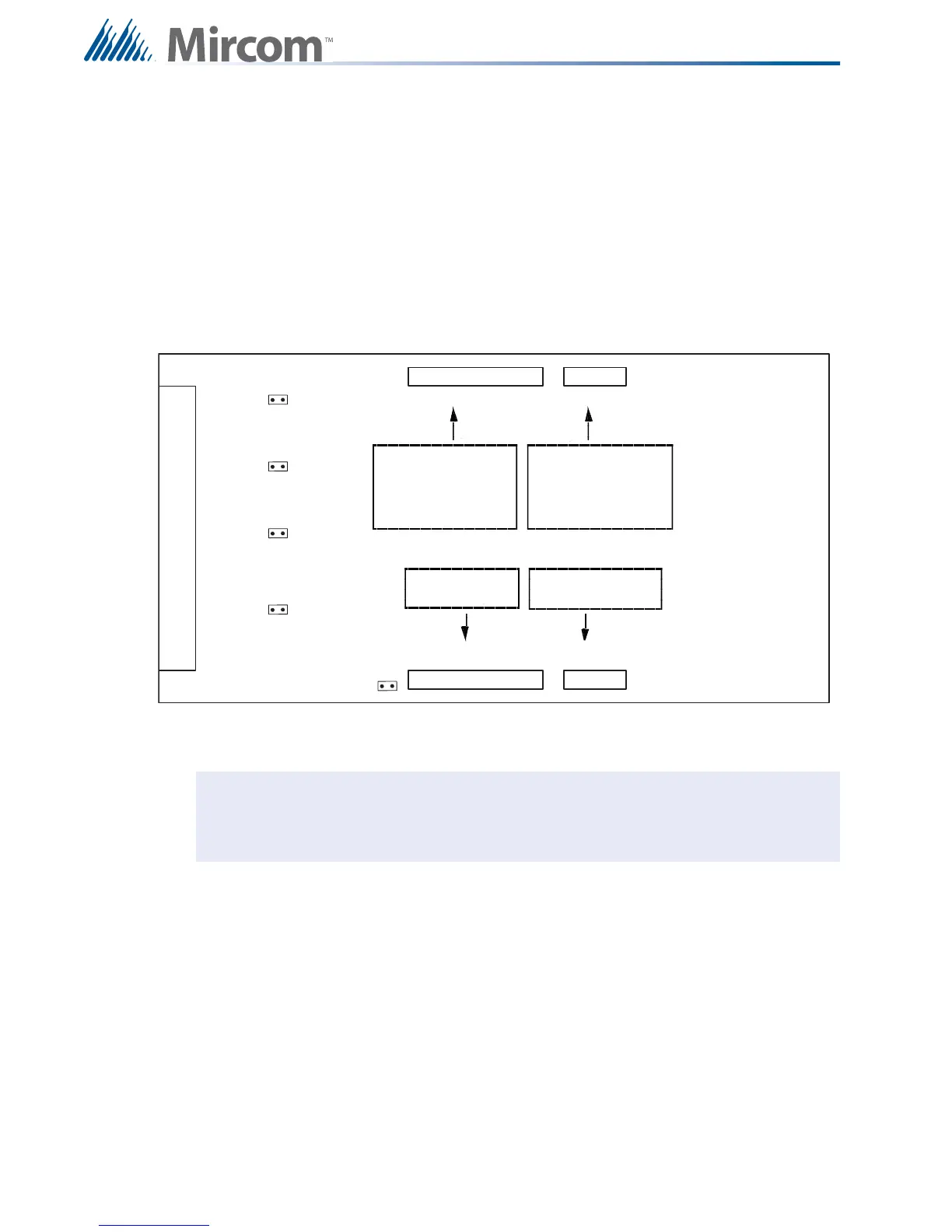
Figure 23 Hardwire Detection Adder Module (DM-1008A)
JW1 Install jumper for Class A (Style D) operation of initiating circuits 1 and 2.
JW2 Install jumper for Class A (Style D) operation of initiating circuits 3 and 4.
JW3 Install jumper for Class A (Style D) operation of initiating circuits 5 and 6.
JW4 Install jumper for Class A (Style D) operation of initiating circuits 7 and 8.
JW5
Remove continuity jumper if there are any more adder modules installed.
Note: For Class A (Style D) operation the FX-2000 must be configured as Class A via
the configuration program.
P1
P3
P4
FI ELD WI RING TERM I NALS
P2
JW 5
JW 4
JW 3
JW 2
JW 1
Data cable to P6 or P5 of
main fire alarm module or to
P12 or P13 of hardwire
loop controller module, or
previous adder module
Powe r connector to P8 of
main fire alarm module,
or to P2 of hardwire loop
controller module, or to
previous adder module
Data connector for
next adder module
Powe r conne ctor fo r
next adder module

 Loading...


