57
Field Wiring
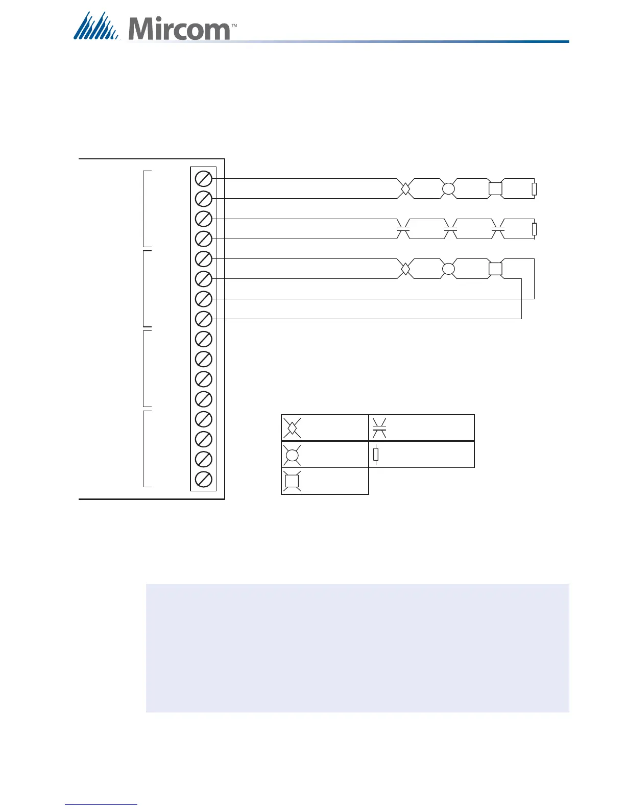
8.2.7 Detection Module (DM-1008A) Terminal Connections
Wire devices to terminals as shown in Figure 39. For further wiring information 8.8 Wiring
Tables and Information. For specifications 12.0 Appendix A: Specifications. For compatible
devices 13.0 Appendix B: Compatible Devices. Jumpers are required for Class A operation.
Figure 39 Hardwire Detection Module (DM-1008A) Terminal Connections
Notes: Terminal blocks are “depluggable” for ease of wiring.
All power limited circuits must use type FPL, FPLR, or FPLP power limited cable.
Initiating circuits are fully supervised and rated for 22 VDC, 3 mA standby, 5 mV
ripple, 50 mA max alarm. They may be configured as required. The alarm
threshold is 21 mA. Maximum loop resistance is 100 ohms, 50 ohms per side.
All conventional hardwire initiating circuits are Compatibility ID "A".
SUPERVISORY OR
WATERFLO W
SWI TCH ( N O)
HEAT DETECTOR
Leg en d: See Appendix B for compatible devices.
SMOKE DETECTOR
3.9K 1/2W ELR LISTED S5434
MODEL MP-300
MANUFACTURED BY MIRCOM
INI1+
INI1-
INI2+
INI2-
INI3+
INI3-
INI4+
INI4-
STYLE B/ D
INI2
STYLE B/ D
INI1
PULL STATION
STYLE B
(CLA SS B)
WIRING
STYLE B
(CLA SS B)
WIRING
STYLE D
(CLA SS A )
WIRING
SUPERVISED INITIATING CIRCUIT #2
(SUPERVISORY OR WATERFLOW ZONE)
(POWER LIMITED)
SUPERVISED INITIATING CIRCUIT #1
(ALARM ZONE) (POWER LIMITED)
SUPERVISED INITIATING CIRCUIT #3
(A L A RM ZON E) SEE STYL E D NOTE ( PO WER LI M I TED)
INI5+
INI5-
INI6+
INI6-
INI7+
INI7-
INI8+
INI8-
STYLE B/ D
INI4
STYLE B/ D
INI3
Style D Note: Initiating circuits in a series
FX-2000 must be either all Style B (Class B)
or Style D (Class A). If Style D is selected, the
number of circuits is cut in half.

 Loading...


