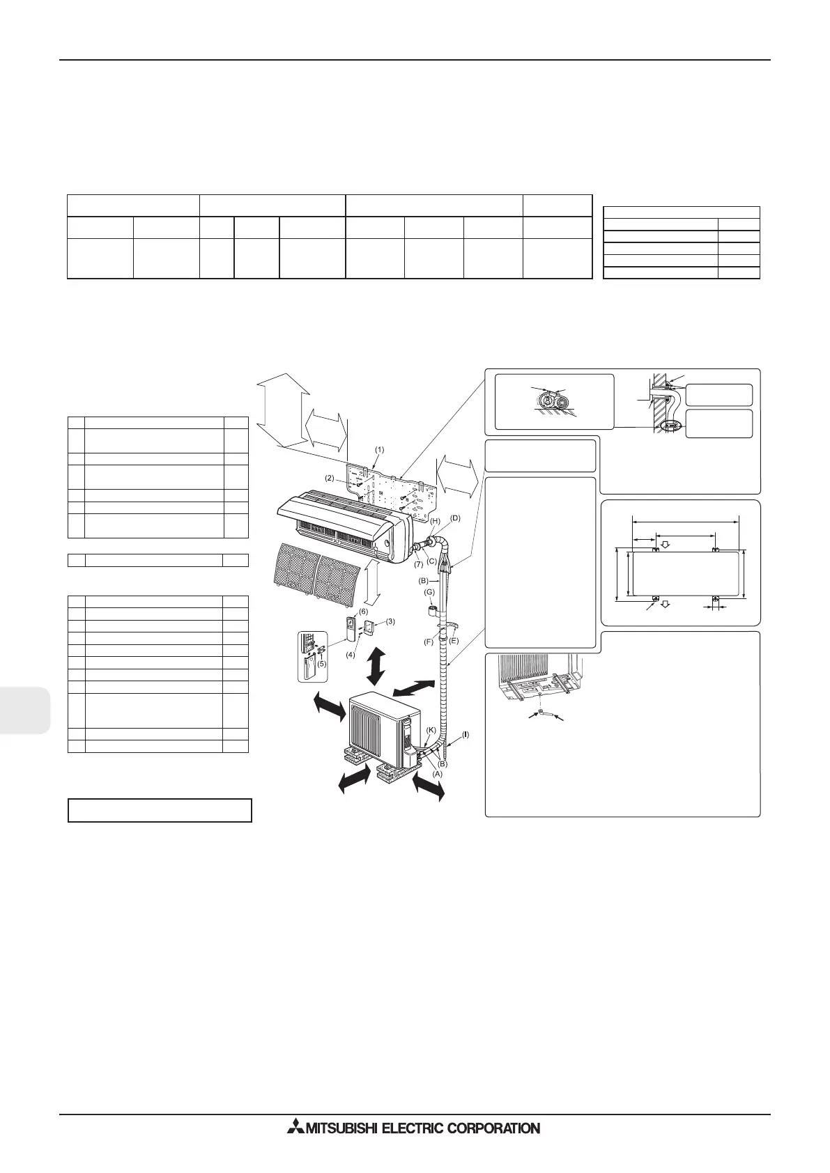
SPECIFICATIONS
*1 Connect to the power switch which has a gap of 3 mm or
more when open to interrupt the source power phase. (When
the power switch is shut off, it must interrupt all phases.)
*2 Use wires in conformity with design 60245 IEC 57.
*3 Never use pipes with thickness less than specified. The
pressure resistance will be insufficient.
*4 Use a copper pipe or a copper-alloy seamless pipe.
*5 Be careful not to crush or bend the pipe during pipe bending.
*6 Refrigerant pipe bending radius must be 100 mm or more.
*7 If pipe length exceeds 7 m, additional refrigerant (R410A)
charge is required. (No additional charge is required for
pipe length less than 7 m.)
Additional refrigerant = A × (pipe length (m) - 7)
*8 Insulation material : Heat resisting foam plastic 0.045 spe
-
cific gravity
*9 Be sure to use the insulation of specified thickness. Exces
-
sive thickness may cause incorrect installation of the indoor
unit and insufficient thickness may cause dew drippage.
Model Power supply *1 Wire specifications *2
Pipe size
(thickness *3, *4)
Indoor unit Outdoor unit
Rated
Voltage
Frequency
Breaker capacity
(Indoor/outdoor)
Indoor Power
supply cord
Outdoor
Power supply
Indoor/outdoor
connecting wire
Gas / Liquid
MSC-GE20VB
MSC-GE25VB
MSC-GE35VB
MU(H)-GA20VB
MU(H)-GA25VB
MU(H)-GA35VB
230 V 50 Hz 10 / 10 A
3-core
1.0 mm
2
3-core
1.0 mm
2
2-core
1.0 mm
2
ø9.52 / 6.35 mm
(0.8 mm)
(GE20, 25/GE35)
Pipe length and height difference
Max. pipe length 20/25 m
Max. height difference 10 m
Max. number of bends *5, *6
10
Refrigerant adjustment A *7 20 g/m
Insulation thickness *8, *9
8 mm
INSTALLATION DIAGRAM
ACCESSORIES
Check the following parts before installation.
<Indoor unit>
(1) Installation plate 1
(2)
Installation plate fixing screw
4 × 25 mm
5
(3) Remote controller holder 1
(4)
Fixing screw for (3)
3.5 × 16 mm (Black)
2
(5) Battery (AAA) for (6) 2
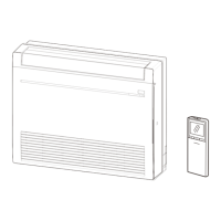
(6) Wireless remote controller 1
(7)
Felt tape
(For left or left-rear piping)
1
<Outdoor unit>
(8) Drain socket <MSH type only> 1
PARTS TO BE PROVIDED
AT YOUR SITE
(A) Indoor/outdoor unit connecting wire* 1
(B) Extension pipe 1
(C) Wall hole sleeve 1
(D) Wall hole cover 1
(E) Pipe fixing band 2 to 5
(F) Fixing screw for (E) 4 x 20 mm 2 to 5
(G) Piping tape 1
(H) Putty 1
(I)
Drain hose
(or soft PVC hose, 15 mm inner
diameter or hard PVC pipe VP16)
1 or 2
(J) Refrigeration oil 1
(K) Power supply cord* 1
Units should be installed by licensed contractor
according to local code requirements.
102/182
mm
or
more
100
mm
or
more
350
mm
or
more
100
mm
or
more
9
7
mm
r
o
/
e
r
o
m
9
01
mm
r
o
e
r
o
m
r
o
f
t
f
e
l
d
n
a t
f
e
l
k
c
a
b
p
i
p
-
g
n
i
g
n
i
s
u
(
)
r
e
c
a
p
s
7
mm
r
o
e
r
o
m
190/182
mm
or
more
* Note:
Place indoor/outdoor unit connecting wire (A)
and power supply cord (K) at least 1 m away
from the TV antenna wire.
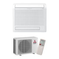
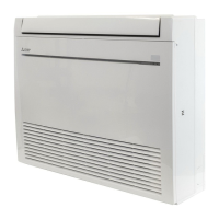
Appearance of the outdoor unit may differ from some models.
100 mm
or more
After the leak test, apply
insulating material tightly
so that there is no gap.
Be sure to use wall hole sleeve (C) to
prevent indoor/outdoor connecting wire
(A) from contacting metal parts in the
wall and to prevent damage by rodents
in case the wall is hollow.
Cut off
the extra
length.
Pipe fixing
band (E)
Fixing
screw (F)
Indoor
unit
Wall hole
sleeve (C)
Wall hole cover (D)
Seal the wall hole
gap with putty (H).
Fix the pipe to
wall with pipe
fixing band (E).
(8)
(I)
Drain piping for outdoor unit
<MSH type only>
• Provide drain piping before indoor and
outdoor piping connection.
• Connect drain hose (I) I.D.15 mm as
shown in the illustration.
• Make sure to provide drain piping with
a downhill grade for easy drain flow.
Note:
Install the unit horizontally.
Do not use drain socket (8) in cold regions.
Drain may freeze and make the fan stop.
The outdoor unit produces condensate
during the heating operation. Select the in-
stallation place to ensure to prevent the
outdoor unit and/or the grounds from being
wet by drain water or damaged by frozen
drain water.
200 mm or more
Air inlet
Air outlet
Outdoor unit installation
2/4-10 mm × 21 mm slot
800 mm
150
mm
500 mm
344.5 mm
285 mm
304-325 mm
40 mm
When the piping is to be
attached to a wall contain
-
ing metals (tin plated) or
metal netting, use a chemi
-
cally treated wooden piece
20 mm or thicker between
the wall and the piping or
wrap 7 to 8 turns of insula
-
tion vinyl tape around the
piping.
To use existing piping, per
-
form COOL operation for
30 minutes and pump down
before removing the old air
conditioner. Remake flare
according to the dimension
for new refrigerant.
(GE20,
25/GE35)
(GE20,
25/GE35)
 Loading...