MEES22K030
QAHV-N-TAU-HPB, YAU-HPB
2
1. Product Specifications
I.1. Product Specifications
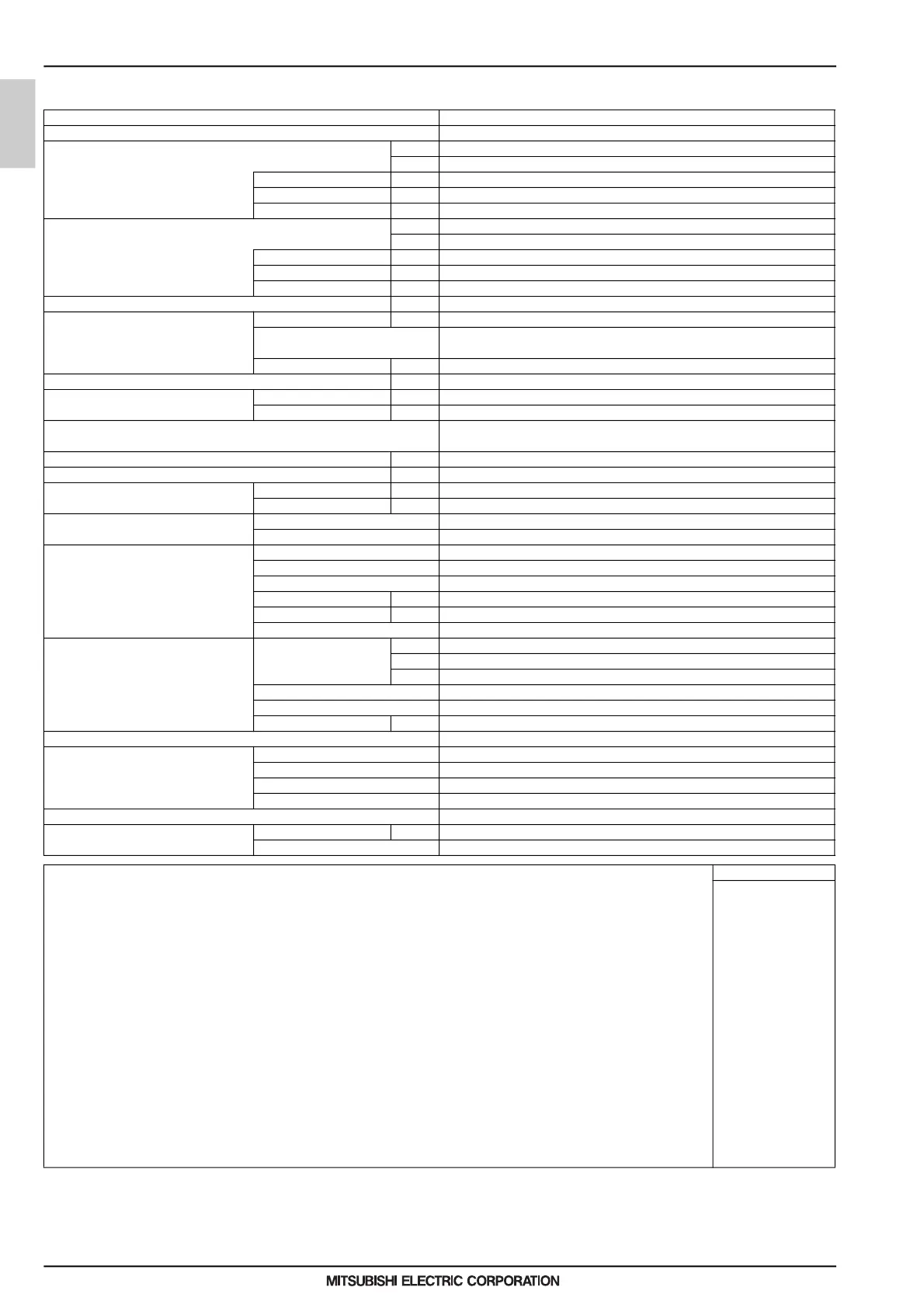
1-1. Specifications
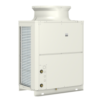
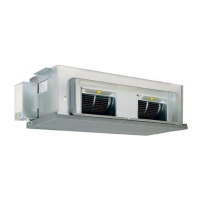
Model QAHV-N136TAU-HPB (-BS)
Power Source 3-phase 3-wire 208-230 V 60 Hz
Capacity *1 BTU/h 136,480
kW 40
Power input kW 9.73
Current input A 30.0-27.2
COP kW/kW 4.11
Capacity *2 BTU/h 136,480
kW 40
Power input kW 10.44
Current input A 32.2–29.1
COP kW/kW 3.83
Allowable external pump head ftAq (kPa) 22.75 (68)
Temperature range *3 Inlet water temperature ºF (ºC) 41–145 (5–63)
Outlet water temperature 120–176ºF (when the secondary side control is enabled: 120–158ºF)
49–80ºC (when the secondary side control is enabled: 49–70ºC)
Outdoor temperature D.B. -13–109°F (-25–43°C)
Sound pressure level (measured 1m below the unit in an anechoic room) *1 *4 dB (A) 56
Water pipe diameter and type Inlet in. (mm) Rc 3/4 (19.05), screw pipe *5
Outlet in. (mm) Rc 3/4 (19.05), screw pipe *5
External finish Acrylic painted steel plate
<MUNSELL 5Y 8/1 or similar>
External dimensions H x W x D in. (mm) 70 × 48-1/16 × 29-15/16 (1,777 × 1,220 × 760)
Net weight lbs (kg) 895 (406)
Design pressure R744 psi (MPa) 2,030 (14)
Water psi (MPa) 72.5 (0.5)
Heat exchanger Water-side Copper tube coil
Air-side Plate fins and copper tubes
Compressor Type Inverter scroll hermetic compressor
Manufacturer MITSUBISHI ELECTRIC CORPORATION
Starting method Inverter
Motor output kW 11.0
Case heater kW 0.045
Lubricant PAG
Fan Air flow rate cfm 7,768
m
3
/min 220
L/s 3,666
Type and quantity Propeller fan × 1
Control and driving mechanism Inverter control, direct driven by motor
Motor output kW 0.75
HIC (Heat inter-changer) circuit Copper pipe
Protection devices High pressure High-pressure sensor and switch set at 2,030 psi (14 MPa)
Inverter circuit Overheat and overcurrent protection
Compressor Overheat protection
Fan motor Thermal switch
Defrosting method Auto-defrost mode (Hot gas)
Refrigerant Type and factory charge lbs (kg) CO
2
(R744) 14.3 lbs (6.5 kg)
Flow and temperature control LEV
Notes: Unit converter
*1.Under normal heating conditions at the outdoor temperature of 80.6ºFDB/71.2ºFWB (27.0ºCDB/21.8ºCWB), the outlet water temperature of 120ºF (49ºC),
and the inlet water temperature of 70ºF (21ºC) This condition is based on 10 CFR.
*2.Under normal heating conditions at the outdoor temperature of 80.6ºFDB/71.2ºFWB (27.0ºCDB/21.8ºCWB), the outlet water temperature of 149ºF (65ºC),
and the inlet water temperature of 70ºF (21ºC) This condition is based on 10 CFR except for outlet water temperature.
(Outlet water temperature is based on typical operating temperatures.)
*3.The temperature difference between inlet water and outlet water must be kept above the following values.
Energy saving operation 1 mode ··· ΔT=50°F (28ºC)
Energy saving operation 2 mode ··· ΔT=50°F (28ºC)
Max capacity operation ··· ΔT=67°F (37ºC)
If the unit is operated with the inlet-outlet water temperature difference at or below the ΔT listed above, the flow rate will reach its maximum, which can adversely
affect the normal operation of the unit and shorten product life.
Note that, regardless of the inlet-outlet water temperature difference (even during operation within the range with the minimum water inlet-outlet temperature
difference), the higher the inlet temperature, the lower the COP.
Keep the inlet water temperature as low as possible to ensure efficient operation.
*4.The sound pressure level is a value measured in an anechoic room in accordance with the conventional method in JRA4060.
*5.PT-NPT reducers are included as accessories.
*Due to continuing improvements, specifications may be subject to change without notice.
*Do not use steel pipes as water pipes.
*Keep the water circulated at all times. Blow the water out of the pipes if the unit will not be used for an extended period of time.
*Do not use ground water or well water.
*Do not install the unit in an environment where the wet bulb temperature exceeds 90ºF (32°C).
*The water circuit must be a closed circuit.
*There is a possibility that the unit may abnormally stop when it operates outside its operating range. Provide backup
(ex.boiler start with error display output signal (blue CN511 1-3)) for abnormal stop.
*In a system in which the ascent rate of inlet water temperature becomes 5 K/min (9ºF/min) or above instantly or 1 K/min (1.8ºF/min) or above continuously,
this model of units cannot be used.
BTU/h =kW x 3,412
cfm =m
3
/min x 35.31
lbs =kg/0.4536
0000006864.BOOK 2 ページ 2022年8月25日 木曜日 午後3時58分
 Loading...