MEES22K030
QAHV-N-TAU-HPB, YAU-HPB
44
5. Wiring Design
5. Wiring Design
5-1. System Configurations
1. Types of control cables
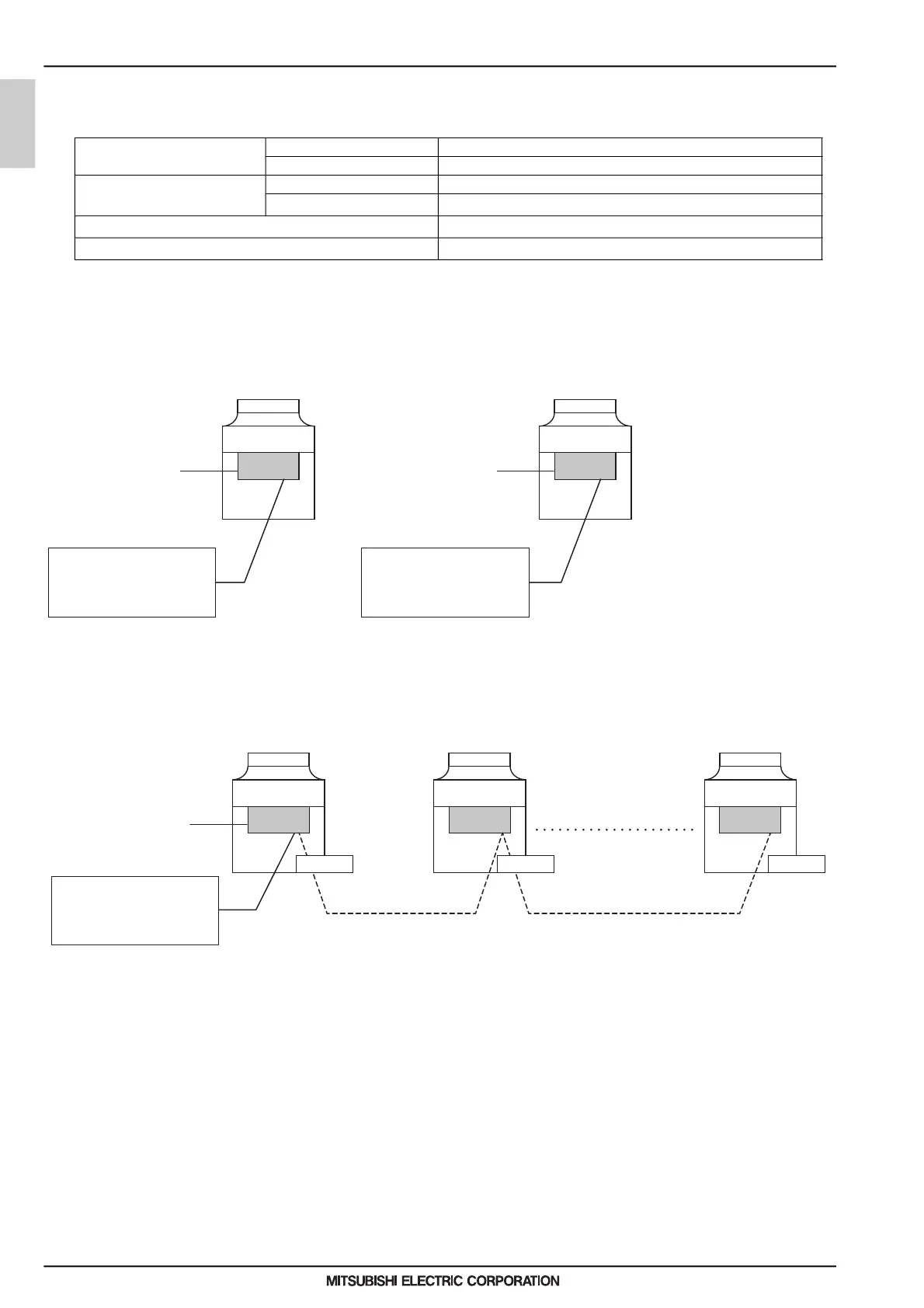
2. System Configuration
(1) Individual system
* Each unit is operated individually by connecting a dry contact switch/relay to each unit.
(2) Multiple system (2-16 units)
* A group of unit that consists of one main unit and up to 15 sub units is operated collectively by connecting an external
water temperature sensor and a dry contact switch/relay to the main unit.
Remote controller cable
Size 0.3 - 1.25 mm² (AWG 22 - 16) (Max. 200 m (656 ft) total)*2
Recommended cable types CVV
M-NET cable between units *1
Size Min. 1.25 mm² (AWG 16) (Max. 120 m (393 ft) total)
Recommended cable types Shielded cable CVVS, CPEVS or MVVS
External input wire size Min. 0.3 mm² (AWG 22)
External output wire size 1.25 mm² (AWG 16)
*1. Use a CVVS or CPEVS cable (Max. total length of 200 m (656 ft)) if there is a source of electrical interference near by (e.g., factory) or the total length of
control wiring exceeds 120 m (393 ft).
*2. When the wiring length exceeds 10 m (32 ft), use wire of 1.25 mm² (AWG 16).
PCB PCB
Unit (MAIN circuit)
External
temperature
sensor
Field-supplied dry contact
switch/relay or remote
controller (PAR-W31MAA) or
centralized controller (AE-200)
Field-supplied dry contact
switch/relay or remote
controller (PAR-W31MAA) or
centralized controller (AE-200)
External
temperature
sensor
Unit (MAIN circuit)
PCB PCB PCB
Unit (MAIN circuit)
MAIN unit
Inter-unit wiring
(M-NET line)
Inter-unit wiring
(M-NET line)
SUB unit
SUB unit(s)
n units
Unit (MAIN circuit) Unit (MAIN circuit)
External
temperature
sensor
Field-supplied dry contact
switch/relay or remote
controller (PAR-W31MAA) or
centralized controller (AE-200)
0000006864.BOOK 44 ページ 2022年8月25日 木曜日 午後3時58分
 Loading...