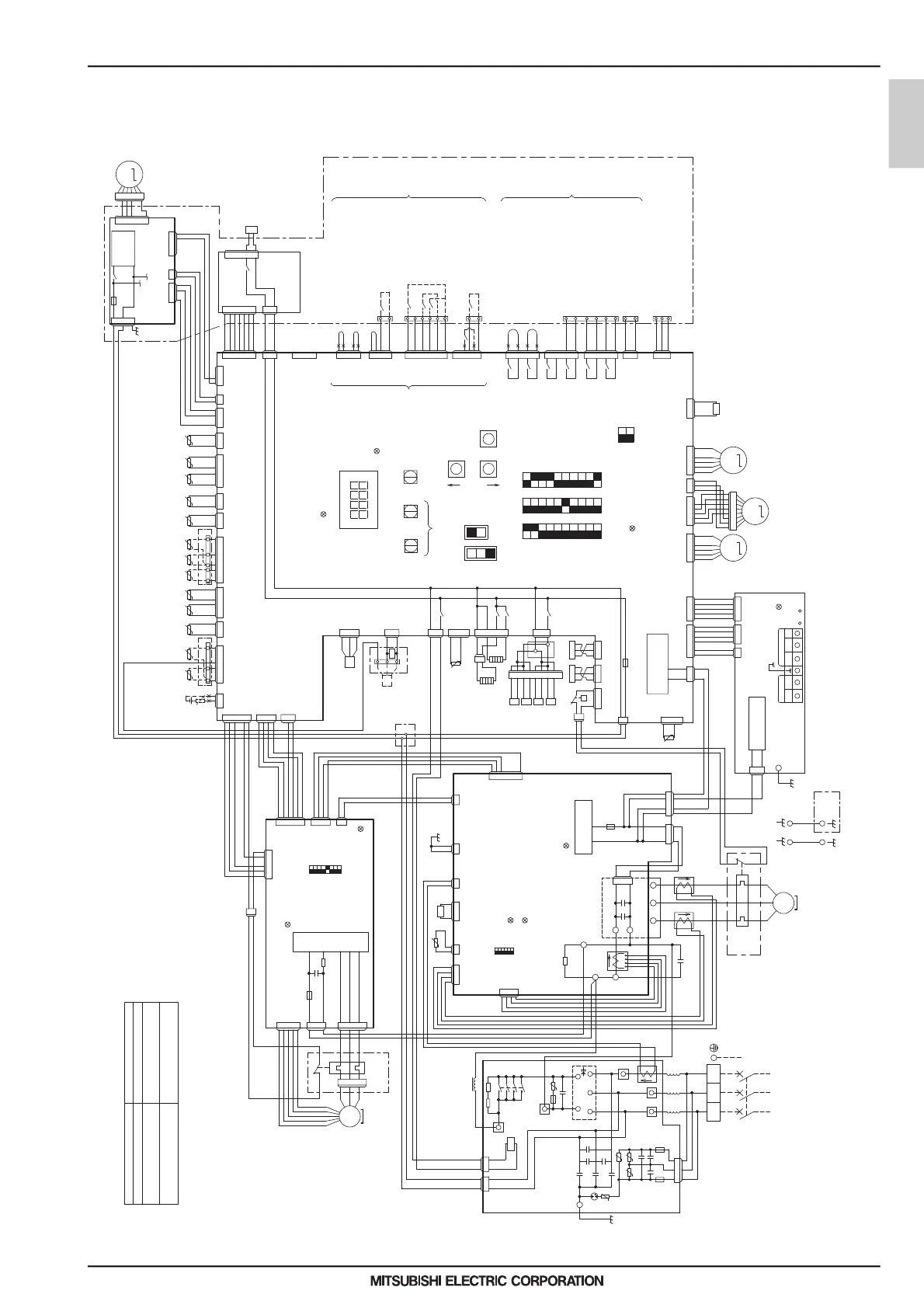
1. Product Specifications
1-4. Electrical Wiring Diagrams
QAHV-N136TAU-HPB (-BS)
t°
t°
t°
t° t° t° t° t° t° t° t° t° t°t°t°t°
REMOTE
SWS2SWS1
LOCAL
OFF
SWP3
SWP2
SWP1
ENTER
UP
GND +5V
CN63HS
GND +5V
CN63LS
red
3
1
2
41
40
X09
X08
63H1
SWU3SWU1 SWU2
ONONON OFFOFFOFF
SW3 SW2 SW1
10
TH11
TH12TH5 TH1TH4TH9 TH2 TH3
PSL1PSH1
3
1
2
2
1
3
321
CNLVB
red
CNLVA
blue
CN401CN404
black
CN405
blue
CN407
red
CN408 CN406
yellow
CN402
green
CNIT
red
CN3A
blue
CN510
CN511
blue
CN512
yellow
CNLVB2
green CNLVC
Relay4-8
board
CNRL
X10
DC280-340V
Rectifier
circuit
F07
AC250V
6.3A T
CNXA1
blue
CND
red
M
MP1
CNOUT1
red
CNXA2
blue
CNXC1
red
TH16
CN62
green
DOWN
LED1:Power
supply
TB3
A/M1 B/M2
Upper controller
AE-200 connecting
terminals
Terminal
between units
(TB3-A/M1,B/M2)
Central
control
S
TP2
A/M1 B/M2
TP1
Transmission
power circuit
TB7
Control
Power circuit
A(to be
prepared)
B(automatic)
LED2:CPU in
operation
Unit address setting
Control Board
LED4:Power supply
LED3:Remote controller
lit while energized
LED1
Compressor
Discharge
Ref temp
Gascooler
Ref temp
Compressor
Suction
Ref temp
Air hex inlet
Ref temp
Outdoor temp
External
Water sensor.2
OFF
ON
SW421
21-24 Low-noise mode
(low noise/by ordinary)
23-24 Run(Run/Stop)
32-33 Hot-water storage
mode(On/Off)
Fan mode
(Forced/Normal)
Capacity mode 2
(short/cut)
Capacity mode 1
(short/cut)
CN142D
blue
CN142C
CN142B
blue
CN142A
black
No-Voltage
contact
input
System error(Normal/Error)
19-20 Demand(On/Off)
External device
connecting terminal
Error display output
Operation display output
No-voltage
contact
output
Optional remote controller
connecting terminal
(Non-polarized)
Emergency signal
(for extra heater)
External device signal
SV5
CN52
CN39
CNAC2
black
CNXB1CNXC1
CNMF
BS08S-
power board
Water outlet
temp
Water inlet
temp
Air hex outlet
Ref temp
TH15
External
Water sensor.1
TH17
External
Water sensor.3
25 26
27 28
30
CN421
black
(+) (-)
IT
TERMINAL
CN105
S1
+12V GND
CNPL3
black
CN502
Flow
sensor.2
Water temp.setting
Analog input
4~20mA/0~10V
1~5V/2~10V
CN422
blue
Shell Ref temp
CN801
yellow
CNS2
yellow
CN102 CNIT
red
CN04
red
Transmission
power board
*9,10
input
Max capacity operation
Energy saving operation 2
Energy saving operation 1
(factory setting)
mode
Capacity mode 1[cut]
Capacity mode 1[short]
Capacity mode 2[cut]
Capacity mode 1,2[short]
*Capacity mode table
14
13
TH14
34
35
*11
T4
TH18
CN409
External INV
CN33
red
TB5
TB9
TB5
TB5
Flow
sensor.1
GND
L3L2L1
Z5
C41
TB42
U
F03
AC250V
6.3A T
CY1
CY2
CY3
-
DS
~
+
~
TB23
TB21
F02
AC250V
6.3A T
L3L2
ACCT3
TB22
L1
TB1
~
CNTYP
Z26
LED1:Normal operation(lit)
/Error(blink)
CNCT3
black
CNCT2
blue
CNFG
blue
INV Board
ON
THHS
OFF
LED4:CPU in operation
1
6
LED3:Remote controller
lit while energized
SW1
CNTH
green
121212213241
23123154
T1 T2
212134 213456 21212134 212314 231421
32412132415
23145
2314675
564213
564213 7
5642137
564213 7
X37
213
12 32451 32413241 234675 1 234675 1234675 1
X07
X06
74
75
72
73
86
87
X05
X04
TB8
321
RA
RB
32465 1 32465 1
19
20
TB6
24
23
32
21
TB6
231
CNPL1
yellow
21
+12V
R11
TB4
S2
12 32314
12
H2
56
H1
X03
X02
CN501
80
81
TB2
2314
231
X01
67589
SV1SV3SV4 SV2
231
CN505
black
X72C
CNWP
green
12 3 21
CNAC
red
F06 AC250V
3.15A T
321
CNDC
pink
2314
32415 324156324156 324156 324156321
6758
M
MVW1
LEV1
M
LEV3
M
TB6
12
CNVOUT
yellow
321
11
10
23145231412
231
2314
CNCT
MC1
U
redwhiteblack
W
V
ACCT1
ACCT2
IPM
N
W
C007
U
P
C008
V
*3
R01
FT-N
MS
3~
231423145
CNVDCCNDC2
F04
AC250V
3.15A T
IPM power
supply circuit
2314
CNDC1
redwhite
SC-P1
+
C1
1
DCCT1
4
black
red
black
DCL
231
CN02
231
CN03
black
Noise
Filter
72C
72C
R1 R2
TB31
red
black
black
Ground
power supply
3~
60Hz
208/230V
DSA1
U
Z4
23145
CN01
F01
AC250V
6.3A T
Z3
Z2
U
U
CX2
U
CX3
CX1
Z1
CX5
CX4
CX6
123
9
8
7
6
5
4
3
2
1
10
9
8
7
6
5
4
3
2
1
10
9
8
7
6
5
4
3
2
1
2
1
TB5
15
Sub box
Service
Valve
33
CNTYP1
black
21
Z21
31
External
Water sensor
(secondary circuit)
LED1:Normal operation(lit)
/Error(blink)
LED4:CPU in operation
SW001
OFF ON
8
1
V
W
U
Fan motor
(Heat exchanger)
CNINV
231465
M
3~
FAN Board
324121324156
CN82
blue
CN80
CN83
black
CN43
yellow
21
CN2
2314675
CN61
green
CN4A
black
CN2A
231465231412
CN81
green
324156
IPM
F05
AC250V
15A T
231
CNVDC
RSH01
C310,C311
2314
CNSNR
5
THR1
Thermal
relay box
THR2
Thermal
relay box
ELB1
3
P
231465
12
DC12V
21
The specification of the product is for the improvement
a previous notice and might change.
 Loading...