6A1 ENGINE (E-W) -
Rocker Cover and Camshaft <MIVEC>
11A-10-3
"
C
A
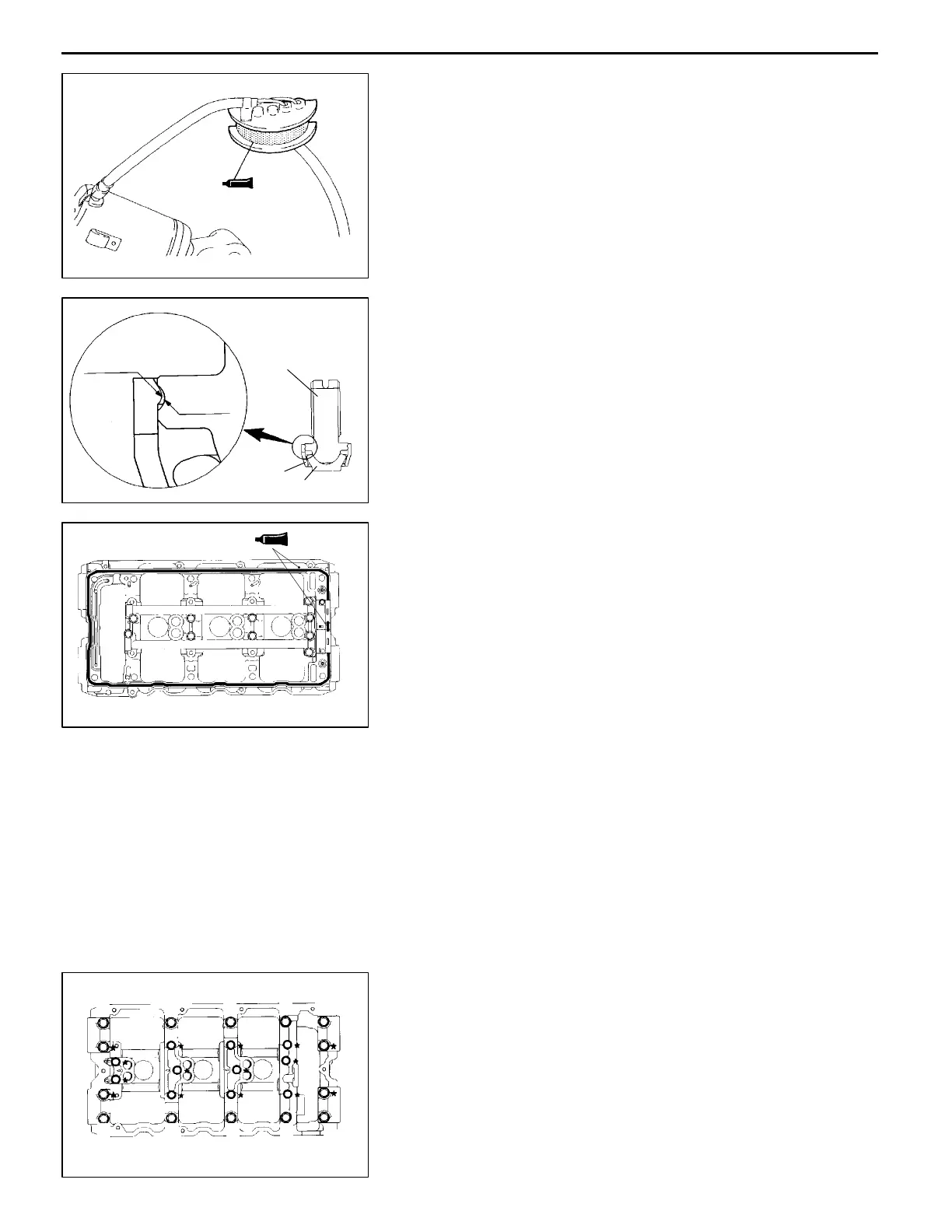
OIL CONTROL VALVE INSTALLATION
(1) Apply the specified sealant to the area shown.
Specified sealant:
3M ATD Part No. 8660 or equivalent
"
D
A
SEMI-CIRCULAR PACKING / CAMSHAFT
HOLDER INSTALLATION
(1) Make sure that the retainer of each adjusting screw is
fitted correctly.
Caution
D
If the protrusion on the retainer is not correctly
fitted in the groove of the screw, the pad could
slip off the retainer.
(2) Apply 3 mm thick bead of foam-in-place gasket (FIPG)
to the gasket surface of the camshaft holder.
Caution
D
Since the FIPG could cause blocking of engine
oil passages, be careful not to apply FIPG to other
locations than specified.
Specified sealant:
Mitsubishi Genuine Part No. MD970389 or
equivalent
(3) Install th e semi-circular packings.
(4) Raise th e rocker arms until the rollers come into contact
with the cams, and install the camshaft holder.
(5) Tighten the bolts in the order indicated in the illustration.
(6) Check the torque of the K-marked bolts. See section "
B
A
for the checking order.
(7) Verify that the pad of each adjusting screw is in place.
PWEE9622
E
Feb. 1997Mitsubishi Motors Corporation
6AE0236
6AE0237
Protrusion
Groove
Screw
Retainer
Pad
6AE0238
6AE0239
106248
7 3 1 5 9
 Loading...


