EasyManua.ls Logo

Mitsubishi AL2-24MR-D User Manual

Mitsubishi AL2-24MR-D
152 pages
To Next Page IconTo Next Page
To Previous Page IconTo Previous Page
Page #119 background imageLoading...
Page #119 background image
α2
Simple Application Controllers
Function Blocks 6
6 - 71
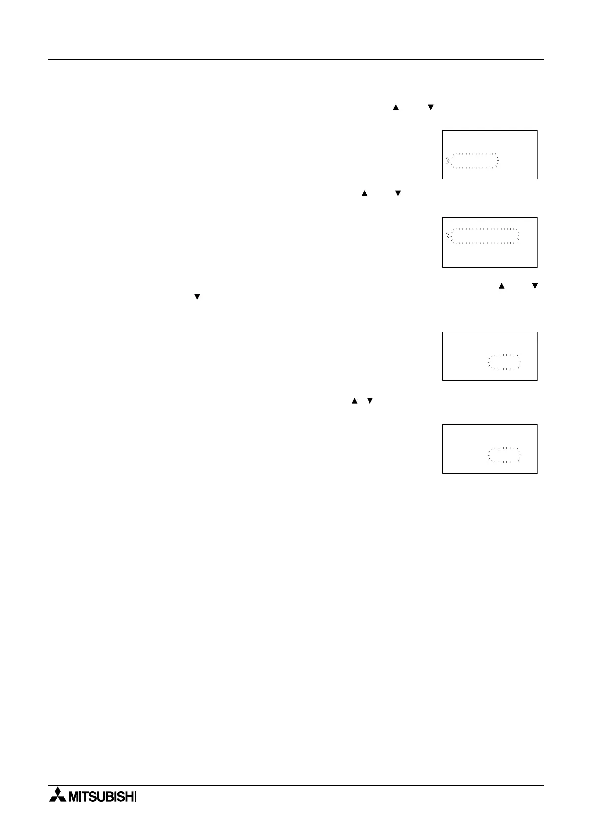
3 ) Press the “OK” key to set the Time unit for the random delayed output.
Choose either a 10ms, 100ms or 1s time interval using the and keys to highlight the
option and press the “OK” key when ready.
4 ) Return to the function block edit screen. Using the “ and ” keys highlight the Setup FB
and press the “OK” key.
5 ) A RandomVal in conjunction with the specified time units allocated earlier can be entered
from pressing the “OK” key having highlighted the RandomVal option using the “ and
keys. Press the ” key hence highlighting the 0s time value and use the “+ or -” keys to
enter a time value. Press the “OK” key to accept and return to the function block setting
screen.
6 ) Highlight the Limit:L,H option and press the “OK” key. A high and low limit can be set for
the Random One Shot function block. Using the “ , , + and -” keys enter values for the
high and low limits in accordance with the time intervals specified earlier.
7 ) Press the “OK” key to accept the High and Low limit subsequently use the “ESC” key to
return to the FBd
Time uni t
100 sm
10 ms
1s
B001 : R SO
Ran do Vmal
Limi t L=,H
B001 : R SO
Rando Vmal
.00s
t= .00s
B001 : R SO
Limi t L:,H
.01sL
=.01s
H
=

Table of Contents

Other manuals for Mitsubishi AL2-24MR-D

Question and Answer IconNeed help?

Do you have a question about the Mitsubishi AL2-24MR-D and is the answer not in the manual?

Mitsubishi AL2-24MR-D Specifications

General IconGeneral
BrandMitsubishi
ModelAL2-24MR-D
CategoryController
LanguageEnglish

Summary

PROGRAMMING MANUAL

Guidelines for the safety of the user and protection of α2 Simple Application controllers

Notes on the symbology used in this manual

Explains the meaning of various symbols used for safety and information throughout the manual.

4. Direct Programming

4.2 Connecting Blocks

Explains the process of connecting output pins from one block to input pins of another.

4.8 The Monitor Mode

Explains how to monitor and update function block values and output status in the Run mode.

5. The Logic Function Blocks

6. Function Blocks

6.3 Boolean block

Details the Boolean function block for logical operations using AND, OR, NAND, XOR, NOT.

6.4 Set/Reset Block

Explains the Set/Reset function block for setting or resetting outputs with priority.

6.7 Delay Block

Explains the Delay function block for delaying output signals based on set times.

6.8 One Shot Block

Describes the One Shot function block for generating a single output pulse for a controlled duration.

6.11 Counter Block

Describes the Counter block for counting input pulses and activating output at a preset limit.

2. Function Block Programming

2.1 Block Type and the FBD base

Introduces the seven item sets for function block programming and the FBD base.

2.2 Programming Methods

Details the two programming methods: Direct Programming and AL-PCS/WIN-E Software.

3. System Menu

3.4 The Edit Menu

Explains how to enter and use the Edit Menu for program adjustments.

7. Lets Make a Program

7.3 Input the Program

Guides on starting program input using front keys and connecting function blocks.

8. Appendix

8.5 Function Blocks

Provides a comprehensive list of all available function blocks with descriptions and memory usage.

Related product manuals