α2
Simple Application Controllers
Appendix 8
8 - 3
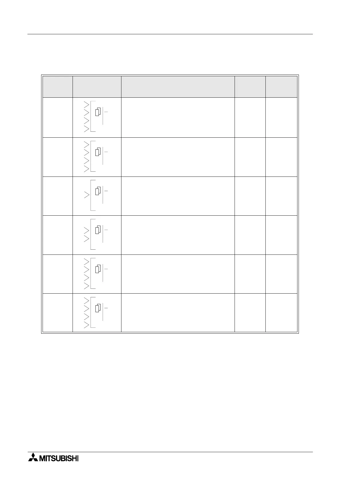
8.4 Boolean Gates
Logic
Block
State
Logic Block
Displayed
Description
Memory
Use
Section
Reference
AND
This function executes logical AND opera-
tion on given input signals. The input sig-
nals connected should be of bit input type
only. 4 Bit input pins and 1 Bit output pin. If
all the inputs are ON then the output is ON,
otherwise output is OFF.
19 Byte 5.1
OR
This function executes logical OR operation
on given input signals. The input signals
connected should be of bit input type only. 4
Bit input pins and 1 Bit output pin. If all the
inputs are OFF then output is OFF, other-
wise output is ON.
19 Byte 5.2
NOT
This function executes logical NOT opera-
tion on given input signal. The input signal
connected should be of bit input type only. 1
Bit input pin and 1 Bit output pin. Output is
negation of Input given.
10 Byte 5.3
XOR
This function executes logical XOR opera-
tion on given input signals. The input sig-
nals connected should be of bit input type
only. 2 Bit input pins and 1 Bit output pin.If
both the inputs are either OFF or ON then
out put is OFF, otherwise output is ON
13 Byte 5.4
NAND
This function executes logical NAND opera-
tion on given input signals. The input sig-
nals connected should be of bit input type
only. 4 Bit input pins and 1 Bit output pin. If
all the inputs are ON then out put is OFF,
otherwise output is ON
19 Byte 5.5
NOR
This function executes logical NOR opera-
tion on given input signals. The input sig-
nals connected should be of bit input type
only. 4 Bit input pins and 1 Bit output pin. If
all the inputs are OFF then out put is ON,
otherwise output is OFF
19 Byte 5.6
00
AND
2
3
O
4
1
00
OR
2
3
O
4
1
00
NT
1
O
00
XOR
1
2
O
00
NAND
2
3
O
4
1
00
NOR
2
3
O
4
1
 Loading...


