EasyManua.ls Logo

Mitsubishi AL2-24MR-D User Manual

Mitsubishi AL2-24MR-D
152 pages
To Next Page IconTo Next Page
To Previous Page IconTo Previous Page
Page #61 background imageLoading...
Page #61 background image
α2
Simple Application Controllers
Function Blocks 6
6 - 13
6.6 Alternate Block
The function block inflicts a reversal of the ON and OFF state of the output as and when the
input is given to the input pin.
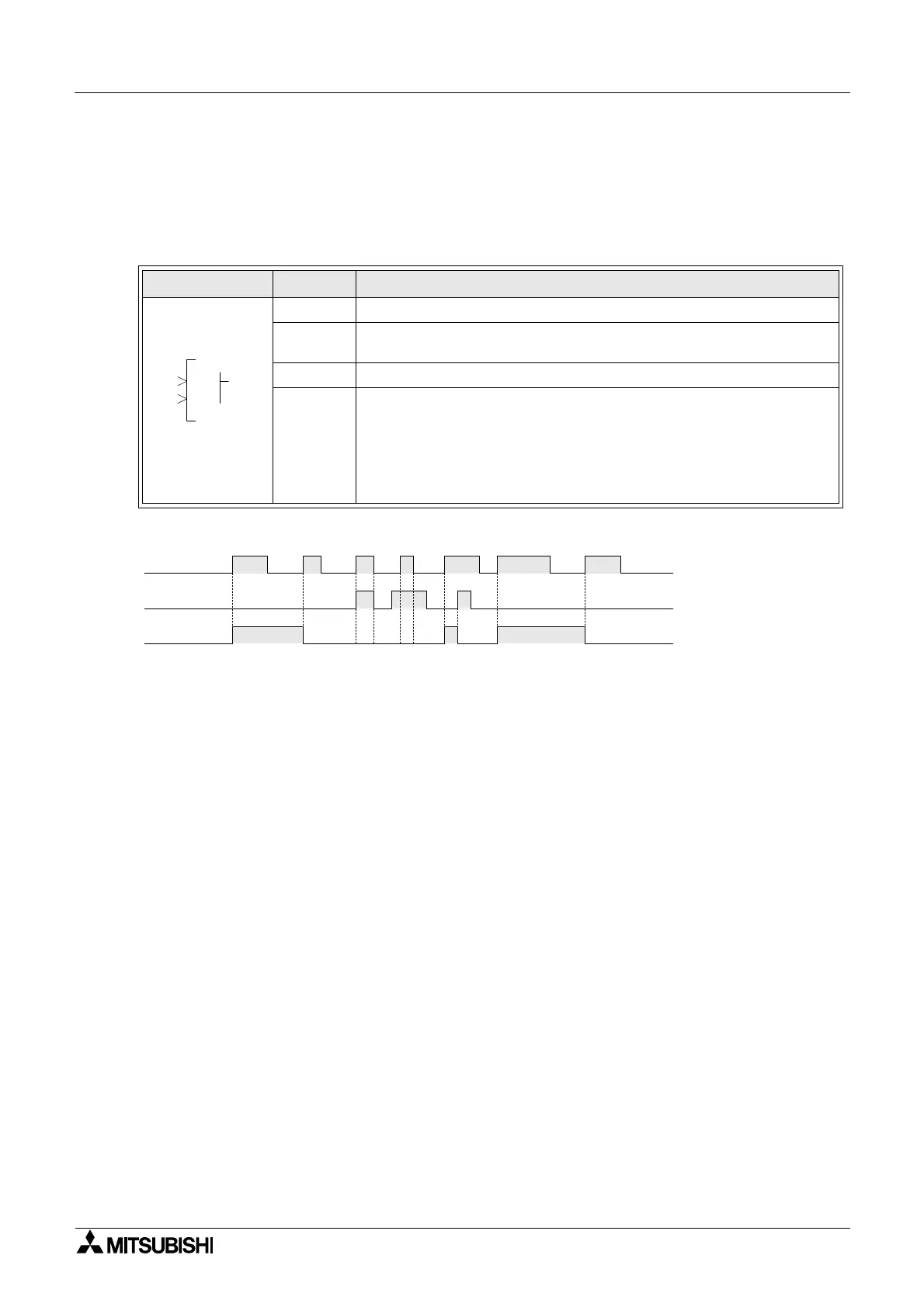
Table 6.6: Alternate Function Block
1 ) Alternate Operation
Function Set Item Description
I Input pin for alternation operation
C
Clear input pin resets the state of the output regardless of the input
given.
FB N/A
Output
The output is affected in the following operation:
1) Reverse the ON/OFF state of the output whenever the input
signal’s ON/OFF operation to the input pin is turned ON (ON to OFF
or OFF to ON)
2) The clear selection resets the output regardless of the input given.
000
LA
OI
C
Input pin I
Input pin C
Output
ON OFF
ON
OFF
ON OFF

Table of Contents

Other manuals for Mitsubishi AL2-24MR-D

Question and Answer IconNeed help?

Do you have a question about the Mitsubishi AL2-24MR-D and is the answer not in the manual?

Mitsubishi AL2-24MR-D Specifications

General IconGeneral
BrandMitsubishi
ModelAL2-24MR-D
CategoryController
LanguageEnglish

Summary

PROGRAMMING MANUAL

Guidelines for the safety of the user and protection of α2 Simple Application controllers

Notes on the symbology used in this manual

Explains the meaning of various symbols used for safety and information throughout the manual.

4. Direct Programming

4.2 Connecting Blocks

Explains the process of connecting output pins from one block to input pins of another.

4.8 The Monitor Mode

Explains how to monitor and update function block values and output status in the Run mode.

5. The Logic Function Blocks

6. Function Blocks

6.3 Boolean block

Details the Boolean function block for logical operations using AND, OR, NAND, XOR, NOT.

6.4 Set/Reset Block

Explains the Set/Reset function block for setting or resetting outputs with priority.

6.7 Delay Block

Explains the Delay function block for delaying output signals based on set times.

6.8 One Shot Block

Describes the One Shot function block for generating a single output pulse for a controlled duration.

6.11 Counter Block

Describes the Counter block for counting input pulses and activating output at a preset limit.

2. Function Block Programming

2.1 Block Type and the FBD base

Introduces the seven item sets for function block programming and the FBD base.

2.2 Programming Methods

Details the two programming methods: Direct Programming and AL-PCS/WIN-E Software.

3. System Menu

3.4 The Edit Menu

Explains how to enter and use the Edit Menu for program adjustments.

7. Lets Make a Program

7.3 Input the Program

Guides on starting program input using front keys and connecting function blocks.

8. Appendix

8.5 Function Blocks

Provides a comprehensive list of all available function blocks with descriptions and memory usage.

Related product manuals