α2
Simple Application Controllers
Function Blocks 6
6 - 14
6.7 Delay Block
The function block delays the signal to an output for a set length of time. The On or Off delays
can be set individually or in combination. Ex. The On Delay Time is set to 5 seconds. The
Delay Block Input signal comes ON; five seconds later the Delay Block Output will come ON.
The Output signal stays ON as long as the Input signal is ON. The Output signal turns OFF at
the same time the Input signal turns OFF. The Clear Input will turn the Output OFF and cancel
the current operation. The Clear pin over-rides the Input pin if both signals are ON
simultaneously.
The On Delay option will delay the Output from turning ON for a set time after the Input comes
ON. The Off Delay will delay the Output from turning OFF for a set time after the Input has
turned OFF.
Table 6.7: Delay Timer Function Block
Note: The ON/OFF delay time cannot be less than one scan time for the controller; otherwise,
the Delay Function Block will not perform its assigned task for the time specified. Users can
monitor the scan time from the
α2 Series Controller. Scan time is dependent on the user-
program; therefore, caution is needed as and when time units are selected.
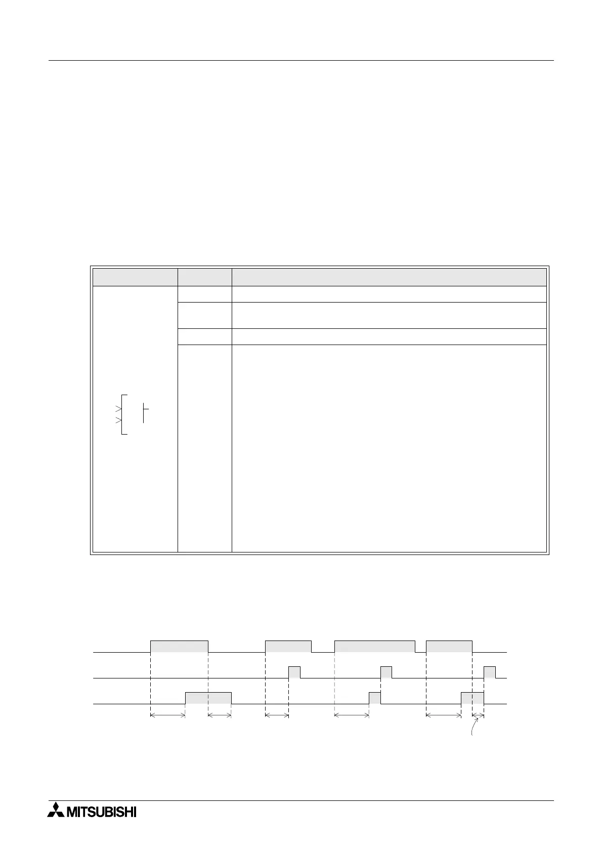
1 ) Delayed Operation
Function Set Item Description
I Input pin for delay timer operation
C
Clear input pin resets the state of the output regardless of the input
given.
FB Time units: 10ms, 100ms or 1s (*Note)
Output
The following items are applicable for the delay function block:
1) The lag time setting for energising the output from a given input
signal can be given a controlled delay time; The starting value has a
range from 0s to 32767s
2) The lag time setting for denergising the output from a given input
signal can be given a controlled delay time; The starting value has a
range from 0s to 32767s
3) If the clear signal of the input pin C is turned on while the delay
function block is in operation consequentially the current value of the
ON delay timer and OFF delay timer resets to “0.” Thus, the output is
turned OFF.
4) The following items are available for other function blocks:
a) On Delay
b) Current On Delay
c) Off Delay
d) Current Off Delay
000
LD
OI
C
P
Input pin I
Input pin C
ON
Output
On delay
Time
Shorter than
On delay time
Off delay
Time
ON OFF
ON
On delay
Time
Shorter than
Off delay time
On delay
Time
 Loading...


