α2
Simple Application Controllers
Lets Make a Program 7
7 - 4
7.3.4 Use the NewFB command
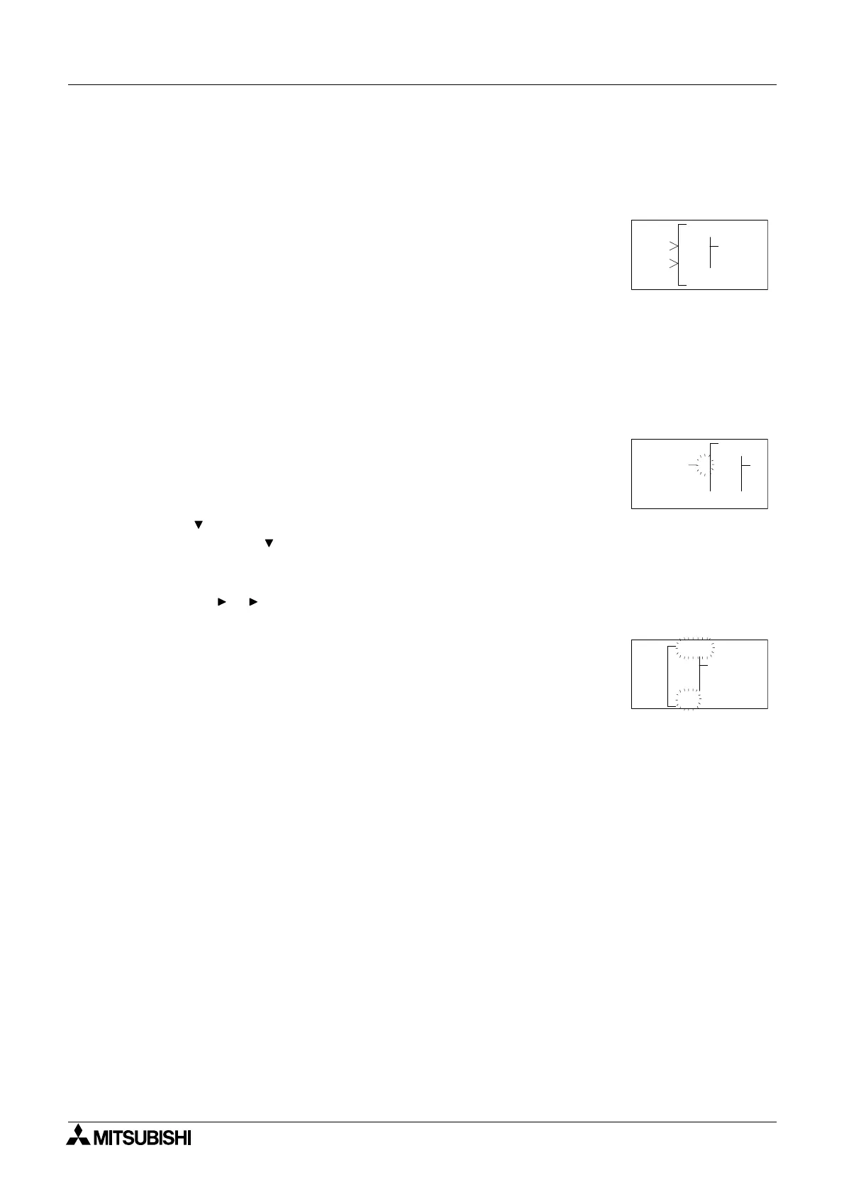
Use the “ESC” key to enter the Edit Menu again. On this occasion enter the New FB option.
Scroll to the Set/Reset FB and select with the “OK” button. The SR diagram should now
appear on the LCD.
7.3.5 Connect the Function Blocks from Right to Left (Section 4.2.2)
Move to the left until one of the two input pins is flashing. The top pin is the Set pin which will
be connected to the OS block. The Reset pin on bottom will be connected to the OR block.
Move to the Set pin and press the “+” key; the available blocks to add will be shown on the left
of the screen. Scroll down through the choices until B01OS is shown (picture). Use the “OK”
to choose the block, then the “OK” key again to confirm the choice.
Use the ( ) arrow to move down to the Reset pin. Connect the OR block using the same pro-
cedure. [“+”, scroll
( ) to B02OR, “OK”, “OK”]
Move to the SR output pin and connect Output O02 using the Left to Right method of connect-
ing blocks. [
( ), ( ), “+”, scroll to O02, “OK”, “OK”].
Move back to the left one space. The following diagram should now be showing on the LCD.
0
RS
03
P
0O030
S
E4
100OS
200OR
noCnect
P
0
RS
0
001
002
P
3
0O2

 Loading...


