EasyManua.ls Logo

Mitsubishi AL2 Series User Manual

Mitsubishi AL2 Series
152 pages
To Next Page IconTo Next Page
To Previous Page IconTo Previous Page
Page #99 background imageLoading...
Page #99 background image
α2
Simple Application Controllers
Function Blocks 6
6 - 51
6.22 Addition Block
The function block is used to summate inputs A and B hence produce the resultant Y.
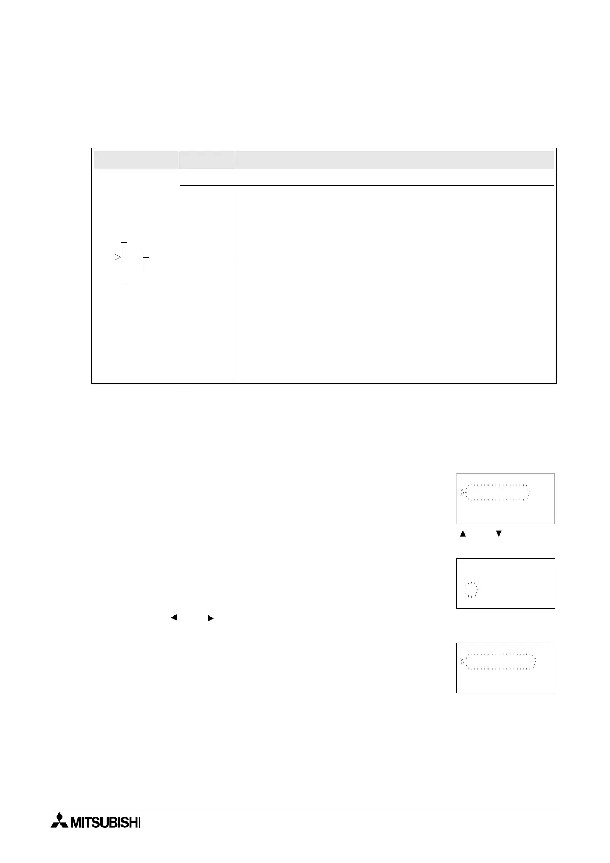
Table 6.22: Addition Function Block
Setup of the Addition Function Block directly from the
α2 Series Controller
1 ) Allocate the input pin to be used for the function block.
2 ) Press the “OK” key with the cursor in the function block. The function block edit screen is
displayed as shown.
3 ) Press the “OK” Key and enter the function block settings using the and ” keys. The
Addition operation Y=A+B must be specified.
4 ) Using the “ and ” keys highlight Constant A and press the “OK” key to enter either a
Directset, Analog In or FB Value.
5 ) Repeat step 4 for Constant B and return to the FBd using the “ESC” key.
Function Set Item Description
I Input pin for addition function block
FB
This function block operates the expression Y=A+B.
The value of Y,A and B is in the range: -32768 to 32767
a) A,B
- Constant value (Setting range:-32768 to 32767
- Analog value
- FB value
Output
1) Word Output
When the input pin is ON, Y=A+B is executed and the word output
will be given the result. When the input pin is OFF the expression is
not executed and the Y value will retain the last result.
2) Bit Output
- Operation result Y<32768: Output pin turned ON and the operation
result Y will be set to -32767
- Operation result Y>32767: Output pin turned ON and the operation
result Y will be set to 32767
000
DA
OI
D
P
B001 : A
Change No
De l e t e FB
DD
Se t up FB
B001 : A DD
Ou t p u t aVl
y=A+B
0
Di rectSet
Ana l og I n
FB Va l ue
B001 : A DD

Table of Contents

Question and Answer IconNeed help?

Do you have a question about the Mitsubishi AL2 Series and is the answer not in the manual?

Mitsubishi AL2 Series Specifications

General IconGeneral
ModelAL2 Series
Digital InputsYes
Digital OutputsYes
TypePLC
ManufacturerMitsubishi
Input Voltage100 to 240 VAC or 24 VDC (depending on model)
Output Voltage24V DC
Number of Inputs8 to 64 (depending on model)
Number of Outputs6 to 64 (depending on model)
Programming LanguageLadder Diagram
Communication PortsRS-232, RS-485, Ethernet (depending on model)
Operating Temperature0 to +55°C
Storage Temperature-20°C to 70°C
Humidity10% to 90% (non-condensing)
WeightVaries depending on the model

Summary

Foreword

Introduction

Special Features and Model Name

Details special features like display messages, function block data, and model name identification.

Function Block Programming

Block Types and FBD Base

Describes the seven sets of items used in function block programming, including inputs and outputs.

Programming Methods

Introduces direct programming and software-based programming for the controller.

System Menu

Stop Mode Top Menu

Details options available when the controller is in Stop mode, such as Run, Setup TS, and ProgEdit.

Run Mode Top Menu

Describes the Top Menu options accessible when the controller is running, like Stop, Monitor, and ClockSet.

Edit Menu and Function Block Edit Menu

Edit Menu Options

Explains options like ProgSize, Jump, New FB, Exit, and Mnemonic within the Edit Menu.

Function Block Editing Options

Details options for editing function blocks: Setup FB, Change No, and Delete FB.

Direct Programming

Block Availability and Connection

Covers block availability and how to connect blocks in direct programming.

Methods for Creating Function Blocks

Describes creating new function blocks using New FB and AddFB options.

Logic Function Blocks

Overview of Logic Gates

Explains the six types of logic blocks: AND, OR, NOT, XOR, NAND, NOR.

Function Blocks Overview

Basic Function Blocks

Describes Boolean, Set/Reset, Pulse, Alternate, Delay, One Shot, Flicker, Time Switch blocks.

Advanced Function Blocks

Details Counter, Compare, Offset, Display, Zone Compare, Schmitt Trigger, Hour Meter blocks.

Lets Make a Program

Option Settings and Function Block Diagram

Covers initial option settings and the basic function block diagram for programming.

Inputting the Program

Step-by-step guide to adding function blocks and creating a program.

Appendix

Associated Manuals

Lists related manuals for the α2 Series Controller.

System Keys and Bits

Explains system keys and system bits used in the controller.

Related product manuals