α2
Simple Application Controllers
Function Blocks 6
6 - 1
6. Function Blocks
The α2 series controller is fundamentally based on function block programming. The blocks
provide a wide range of possible operations and have been preprogrammed for ease of use.
Some Function Blocks have parameters that can be tailored to meet individual requirements in
the programs. Each function block will have a description of the Block’s purpose, a diagram of
how the Block will appear on-screen, and a description of the inputs, outputs, and available
options.
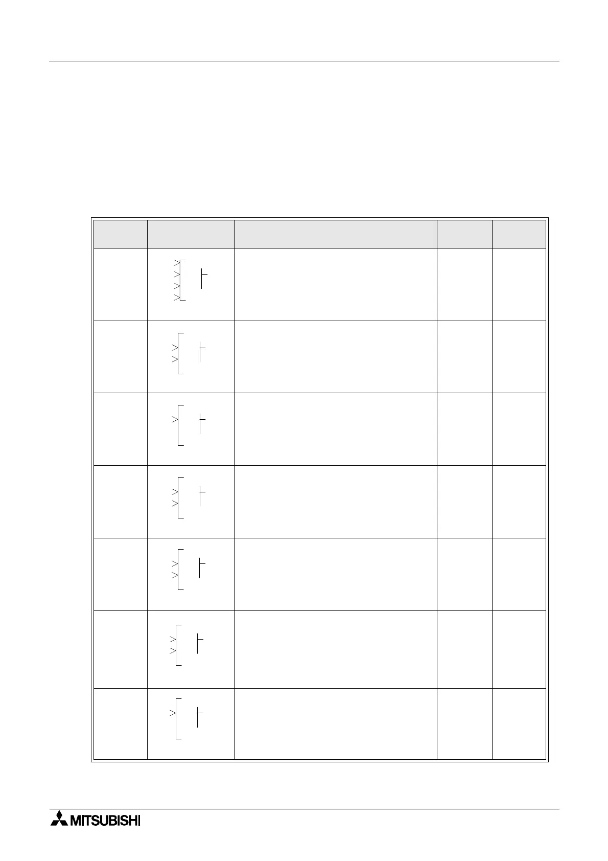
Table 6.1: Function Block List
FB Name FB Symbol Description of Function Block
Memory
Use
Section
Boolean
[BL]
The Boolean Function Block uses Boolean
algebra to control the ON/OFF state of an
output. An operational expression consists
of either the AND, OR, NOR, XOR or NOT
form.
*1 6.3
Set/Reset
[SR]
The Set/Reset Function Block either holds
an output ON (set) or releases the output
OFF (reset.) Priority can be given to either
input pin if both inputs have been energised
simultaneously. The default priority setting
is dedicated to the reset input pin.
14 Byte 6.4
Pulse
[PL]
The Pulse Function Block sends a single
pulse to the output pin if the input pin
receives either an “ON to OFF”, “OFF to
ON” or “ON to OFF And OFF to ON” input
operation.
10 Byte 6.5
Alternate
[AL]
The Alternate Function Block is used to
reverse the ON and OFF state of the output
as and when the input pin receives a signal.
The output will be set ON when the input
pin goes high and remain ON until the input
receives the second rising edge.
13 Byte 6.6
Delay
[DL]
The Delay Function Block provides an ON
delay timer and an OFF delay timer. Time
intervals for either situation can be set. The
time unit can be set to 10ms, 100ms or 1s
increments.
19 Byte 6.7
One Shot
[OS]
The One Shot Function Block awaits a
signal supplied to the input pin thereafter
setting the output according to the specified
time. The timing parameters control the
state of the output (depending on the
priority setting). The time unit can be set to
10ms, 100ms or 1s increments.
17 Byte 6.8
Flicker
[FL]
The Flicker Function Block changes the ON
and OFF state of the output according to a
preset flicker time. The time unit can be set
to 10ms, 100ms or 1s increments.
19 Byte 6.9
0001
LB
O2
3
4
P
000
RS
OS
R
P
000
LP
OI P
000
LA
OI
C
000
LD
OI
C
P
000
SO
OI
C
P
000
LF
OI P

 Loading...


