EasyManua.ls Logo

Mitsubishi AL2 Series User Manual

Mitsubishi AL2 Series
152 pages
To Next Page IconTo Next Page
To Previous Page IconTo Previous Page
Page #15 background imageLoading...
Page #15 background image
α2
Simple Application Controllers
Function Block Programming 2
2 - 3
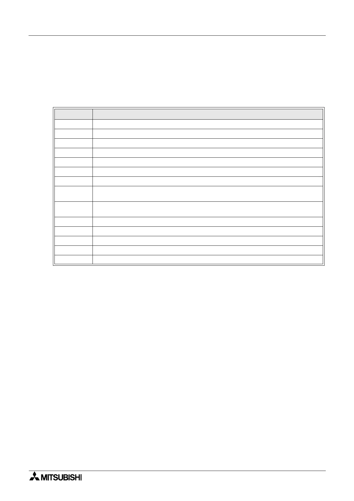
2.1.3 System Memory Bits
These System Memory Bits can provide predefined signals - Always On, Always Off, 0.5
second On, 0.5 second Off, or provide information about the Real Time Clock time or errors
etc. There are fourteen Memory bits that are referenced to M01, M02, ... M14.
Table 2.3: System Bits for the
α2 Series Controller
2.1.4 Function Blocks
Programming the α2 Series Controller is based upon the combination of different function
blocks. They process the information received from the previously mentioned inputs and
control the system Outputs. They can also provide input signals or information to other
function blocks using word outputs pins. To make programming easier, the Function Blocks
have all been preprogrammed. Therefore, parameters within each function block dialog box
can be set according to the intended application. There are 38 Function Blocks available, they
are described in detail throughout Chapters 5 and 6.
System Bit Description
M01 Always “ON”.
M02 Always “OFF”.
M03 Alternate - 0.5 seconds “ON”, 0.5 seconds “OFF”.
M04 “ON” when Real Time Clock data error occurs.
M05 “ON” when Summer time schedule is activated.
M06 “ON” when AS-interface communication Error occurs.
M07 “ON” when communication Error caused by AS-interface power failure occurs.
M08
“ON” when Stop mode turns to Run mode in the α2 Series. The “ON” signal acts as a
pulse output and then turns “OFF”.
M09
“OFF” when Stop mode turns to Run mode in the α2 Series. The “OFF” signal acts as
a pulse output and then turns “ON”.
M10 Reserved
M11 Reserved
M12 “ON” when CD (DCD) signal is turned ON (receiving CD signal from the modem.)
M13 “ON” when it is possible to access the GSM network.
M14 “ON” when the α2 series controller is accessed via GSM

Table of Contents

Question and Answer IconNeed help?

Do you have a question about the Mitsubishi AL2 Series and is the answer not in the manual?

Mitsubishi AL2 Series Specifications

General IconGeneral
ModelAL2 Series
Digital InputsYes
Digital OutputsYes
TypePLC
ManufacturerMitsubishi
Input Voltage100 to 240 VAC or 24 VDC (depending on model)
Output Voltage24V DC
Number of Inputs8 to 64 (depending on model)
Number of Outputs6 to 64 (depending on model)
Programming LanguageLadder Diagram
Communication PortsRS-232, RS-485, Ethernet (depending on model)
Operating Temperature0 to +55°C
Storage Temperature-20°C to 70°C
Humidity10% to 90% (non-condensing)
WeightVaries depending on the model

Summary

Foreword

Introduction

Special Features and Model Name

Details special features like display messages, function block data, and model name identification.

Function Block Programming

Block Types and FBD Base

Describes the seven sets of items used in function block programming, including inputs and outputs.

Programming Methods

Introduces direct programming and software-based programming for the controller.

System Menu

Stop Mode Top Menu

Details options available when the controller is in Stop mode, such as Run, Setup TS, and ProgEdit.

Run Mode Top Menu

Describes the Top Menu options accessible when the controller is running, like Stop, Monitor, and ClockSet.

Edit Menu and Function Block Edit Menu

Edit Menu Options

Explains options like ProgSize, Jump, New FB, Exit, and Mnemonic within the Edit Menu.

Function Block Editing Options

Details options for editing function blocks: Setup FB, Change No, and Delete FB.

Direct Programming

Block Availability and Connection

Covers block availability and how to connect blocks in direct programming.

Methods for Creating Function Blocks

Describes creating new function blocks using New FB and AddFB options.

Logic Function Blocks

Overview of Logic Gates

Explains the six types of logic blocks: AND, OR, NOT, XOR, NAND, NOR.

Function Blocks Overview

Basic Function Blocks

Describes Boolean, Set/Reset, Pulse, Alternate, Delay, One Shot, Flicker, Time Switch blocks.

Advanced Function Blocks

Details Counter, Compare, Offset, Display, Zone Compare, Schmitt Trigger, Hour Meter blocks.

Lets Make a Program

Option Settings and Function Block Diagram

Covers initial option settings and the basic function block diagram for programming.

Inputting the Program

Step-by-step guide to adding function blocks and creating a program.

Appendix

Associated Manuals

Lists related manuals for the α2 Series Controller.

System Keys and Bits

Explains system keys and system bits used in the controller.

Related product manuals