(iii)
(iv)
(VI
(vi)
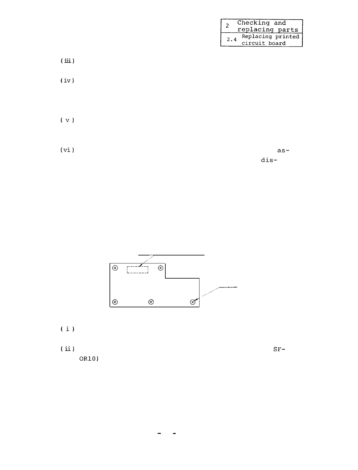
Remove the five nails on the SF-CA card (left figure)
and loosen the two screws.
Raise and remove the SF-CA card from the hinge panel.
Last,
insert your fingers into the cavities (2 posi-
tions) on the hinge panel and remove the entire SF-CA
card from the hinge panel.
By referencing the right figure, loosen the four
screws which fasten the SF-PW (power supply) and
remove it.
After replacing the SF-PW (power supply)
semble the parts in the reverse order of
assembling procedure.
module,
as-
the dis-
(Note) When mounting the SF-CA card, push the connec-
tor by your fingers from the front side of the
card so that the connector on the rear side of
the SF-CA card is securely connected to the
SF-CA card.
2.4.2
Replacing SF-OR or SF-OR10 card
Connector (Rear side)
/
/
0
,---1*I-,
i______;
0
Screw
,'
A7
/
0 0
(
i)
By referencing Appendix 2-l or 2-2, remove the con-
nectors (CON4, CONB, CONAA, and CONC).
(ii)
Loosen the five screws and remove the SF-OR (or
SF-
ORlO)
card.
-
62
-