2.7
Replacing transistor module and diode stack
(i) Disconnect the leads which are connected to the
transistor module or stack and remove them from the
heat radiation fin.
(Note) Since part of the terminals G and E of the
transistor module is of the insert type, when
removing them,
take care of it.
(ii) Equally apply silicone grease on the rear side of
.
.
the module or stack.
(iii)
At the specified tightening torque (see the following
table),
mount the devices in the same direction as
the old ones and then connect the leads.
(Note) Put on the tube on the terminal G of the
tran-
sis
tor module.
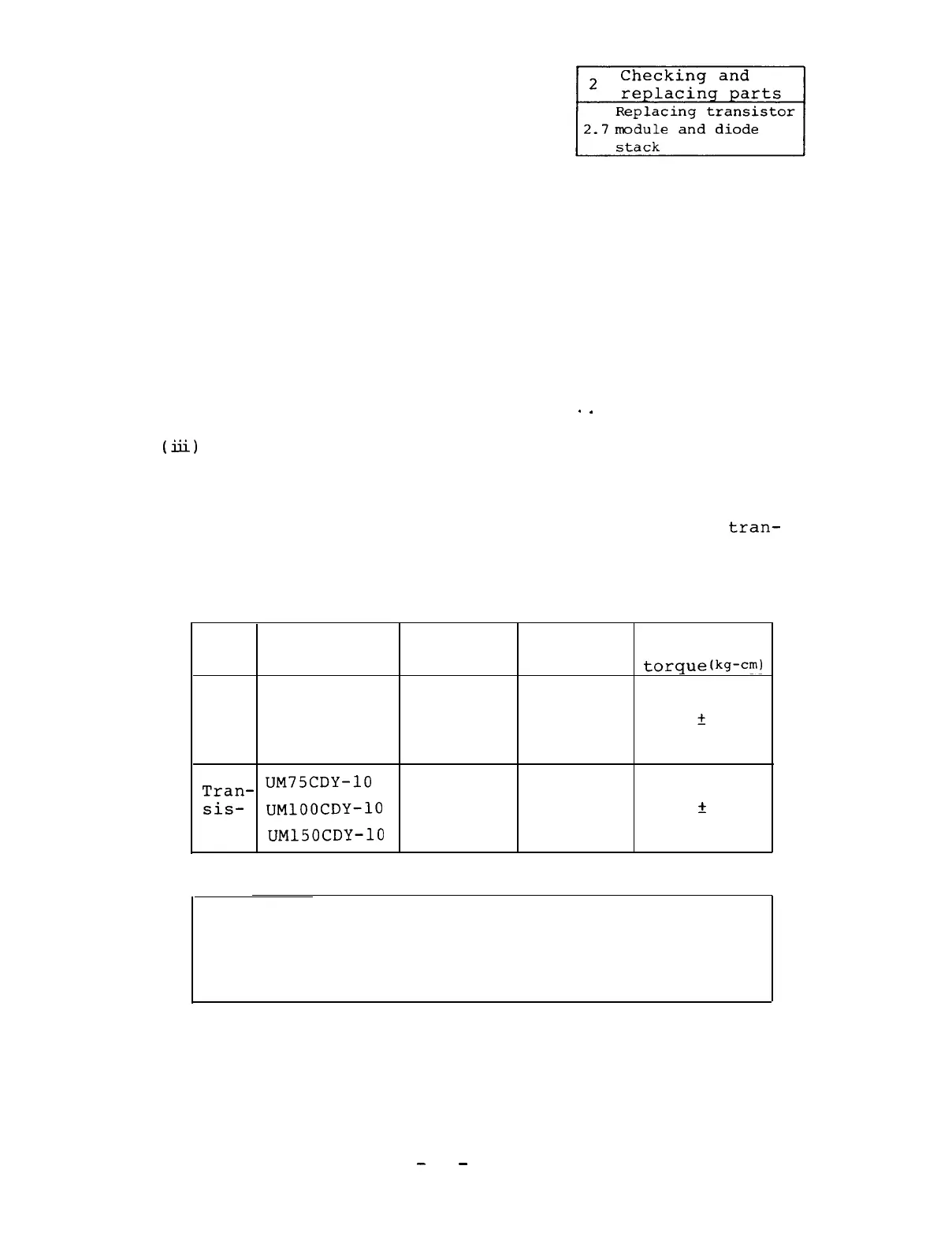
Tightening torque table
Maximum
Recommended
Model
Screw size tightening tightening
torque
torque(kg-cm)
PT768
(kg-cm)
Diode
PD608
M5 x 0.8
20
17
?
2
PD1008
Tran-
UM75CDY-10
sis-
UMlOOCDY-10
M5 x 0.8
20
17
f
2
tor
UM150CDY-10
(Note)
Since the diodes and transistors used in the
equipment conform with the detail specific-
ations,
they which are replaced or prepared
for spares should be purchased from Mitsu-
bishi.
-
70
-

 Loading...