3.
SPECJRCATlONS
/MELSEC-A
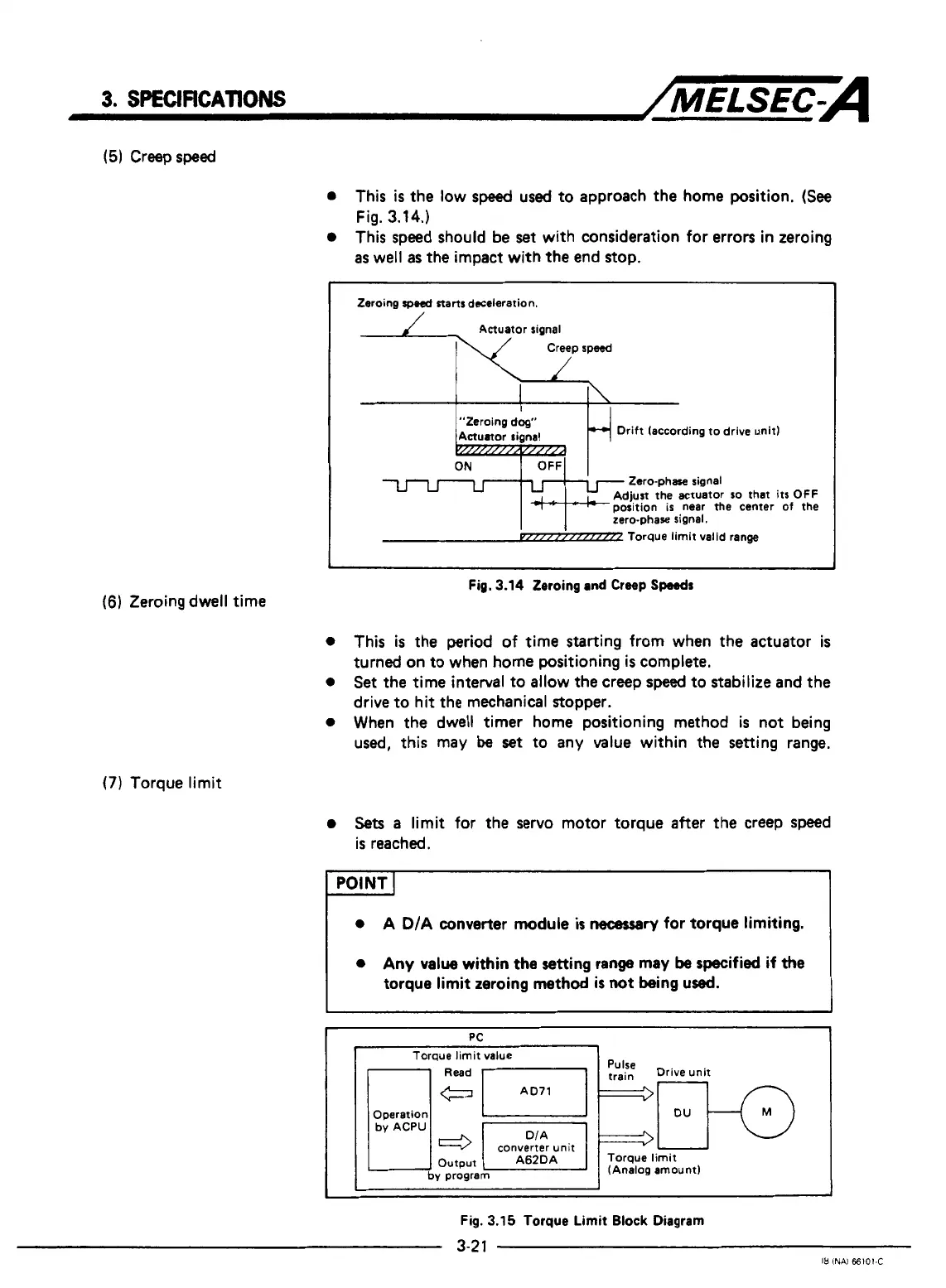
(5)
Creep
speed
0
This
is
the low
speed
used
to approach the home position.
(See
0
This speed should be
set
with consideration for errors in zeroing
Fig.
3.14.)
as
well
as
the impact with the end stop.
I
1
Zeroing
speed
starts
deceleration.
Drift [according to drive unit)
Zero-phase signal
Adjust the actuator
so
that it5
OFF
position is near
the
center
of
the
zero-phase signal.
P//I////I////R
Torque
limit valid range
1
J
Fig.
3.14
Zeroing and
Creep
Speeds
(6)
Zeroing dwell time
0
This
is
the period
of
time starting from when the actuator
is
turned on to when home positioning
is
complete.
0
Set
the
time interval to allow the creep
speed
to stabilize and the
drive to hit the mechanical stopper.
0
When
the
dwell timer home positioning method
is
not being
used,
this may
be
set to any value within the setting range.
(7)
Torque limit
0
Sets
a
limit for the
servo
motor torque after the creep speed
is reached.
I
POINT
I
I
I
I
I
0
A D/A converter module
is
necessary
for
torque limiting.
0
Any
value
within
the
setting range
may
be
specified
if
the
torque limit zeroing method
is
not
being used.
Y
PC
i
I
Torque limit value
1-1
Read
71
I
r:i::
Drive unit
Operation
converter unit
by
program
(Analog amount)
c
I
I
Fig.
3.15
Torque
Limit
Block
Diagram
3-21
IB
INAi
66101-C

 Loading...


