2 Robot arm
Tooling 2-15
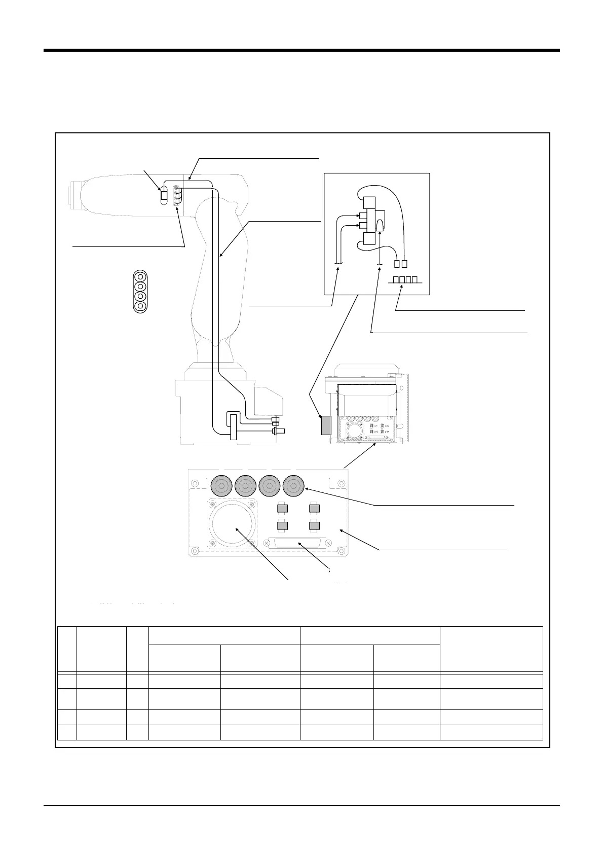
2.5 Tooling
2.5.1 Wiring and piping for hand
Shows the wiring and piping configuration for a standard-equipped hand.
Fig.2-5 : Wiring and piping for hand
1~4 : 2次配管用継手
(φ4用)
電磁弁セット(オプション)
取付部分
ア
イ
2次配管エアホース
(φ4×4本)
2次配管エアホース
(φ4) 注2)
1次配管エアホース
(φ6×1本) 注2)
GR1~GR4 (イと接続)
ハンド出力用コネクタ
GR1~GR4 (イと接続)
ハンド出力用コネクタ
AIR IN 1~4 (アと接続)
2次配管用継手(φ4)
機器間ケーブル
(信号用)コネクタ
機器間ケーブル
(電源用)コネクタ
ハンド出力用コネクタ番号
ハンド用継手番号
注1)電磁弁セットに接続するφ4エアホースは
お客様でご準備ください。
[拡大図]
AIR OUT
1
2
3
4
1
GR1
2 3 4
GR3
GR2
GR4
ハンド入力信号ケーブル
( AWG#24(0.2mm2) x 2芯4本{)
ハンド入力信号コネクタ
(CON1H)
注)図の反対側
Connector and pneumatic coupling
No Name
Qty.
Robot side(Robot arm side) Counter side (customer-prepared)
Manufacturer
Connectors,
couplings
Connector pins Connector Connector pins
(1) Connector 1 1-1903131-6 1903112-2 1-1827864-6 1827587-2
AMP
(2) Connector 4 SMP-02V-BC BHF-001GI-0.8BS SMR-02V-B BYM-001T-0.6
Japan solderless terminal MFG.
Co.,LTD
(3) Coupling 4 KJS04-M3 - - -
SMC. Co.,LTD
(4) Coupling 4 UKB4 - - -
Koganei
(3)1 to 4 : Secondary piping
couplings (φ4)
(1)Hand input signal connectors
Solenoid valve set (optional)
installation section
Secondary piping
hoses (φ4*4)
GR1 to GR4: Connect to the b)
Hand output connector
Primary piping pneumatic hoses(φ6*1)
Note2)
Magnification
Secondary piping
pneumatic hoses
(φ4) Note2)
(2)GR1 to GR4:Connect to the b)
Hand output connector
(4)AIR IN 1 to 4:Connect to the a)
Secondary piping air coupling(φ4)
Machine cable connector
(Signals)
Machine cable connector
(Power supply)
Number of connector for hand output.
Number of coupling for hand.
Note1)The user must prepare the φ4 pneumatic hoses
for connecting to the solenoid valve set.
a)
b)
Opposite side of figure
AWG24 (0.2mm
2
) x 2 core: Four
Hand input signal cables

 Loading...


