3-70 Magnet contactor control connector output (AXMC) for addition axes
3 Controller
3.10 Magnet contactor control connector output (AXMC) for addition axes
When an additional axis is used, the servo ON/OFF status of the additional axis can be synchronized with the
servo ON/OFF status of the robot itself by using the output contact (AXMC) provided on the rear or inside of the
controller and configuring a circuit so that the power to the servo amplifier for the additional axis can be turned
off when this output is open.
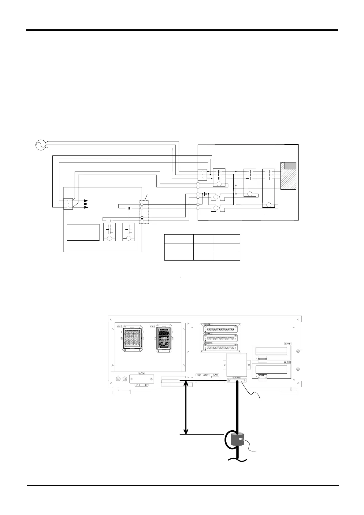
An example circuit and an image of how to connect the controller connector are shown below. When you are using
an additional axis, please perform appropriate circuit connections by referring to these drawings.
Refer to the separate "Additional axis interface Instruction Manual" for details on the additional axis function.
Note1) you use the addition axis function as a user mechanism who became independent of the robot arm, please
do not connect this output signal. Servo-on of the user mechanism may be unable.
Fig.3-26 : Example of circuit for addition axes of Magnet contactor control output
(1) CR750 controller
Fig.3-27 : AXMC terminal connector (CR750)
MC2
NV
MC MC1
内部回路へ
<コントローラ>
内部サーボ電源用
コンタクタ接点より
AXMC出力
<走行軸(付加軸)アンプボックス>
NV
2)コントローラ内蔵漏電遮断器(NV)の2次側より、
MC同期用電源を取り出す。
AXMC21
注2)
1)付加軸アンプボックス内蔵漏電遮断器(NV)の2次側より、コントローラ電源を取り出す。
AXMC11
注1)
88
CNUSRコネクタ
アンプ
DC24V
AXMC12
AXMC22
注2)
注1)コネクタとピン番号を以下に示します。
AXMC11
AXMC12
AXMC21
AXMC22
注2)ロボットがアラームの発生などでサーボOFFしたとき、本出力(接点)が開放します。
<接点容量>
DC24V/10mA~100mA
信号名
ピン番号
コネクタ
CNUSR2
45
19
44
20
CNUSR2
1) Get the power supply for the controller from the secondary terminal
of short circuit breaker (NV) built in the addition axis amplifier box.
2) Get the power supply for the MC synchronization from the sec
-
ondary terminal of short circuit breaker (NV) built in the control
-
ler.
To the
internal
circuit
AXMC is output
from the contact
for internal servo
power supplies.
<Controller>
CNUSR connector
Note1)
Note2)
Note2)
Amplifier
<Addition axis amplifier box><Addition axis amplifier box>
Signal
Connector Pin number
Note1) Connector and Pin number
Note2) This output is opened, if the robot turns off the servo by occurrence of alarm etc.
<Electric specification>
DC24V/10mA to 100mA
30cm以内
フェライトコア
2回通し
CNUSR2コネクタ
*Connects with CNUSR2 connector
with soldering. Refer to
Page 56 "Fig.
3-12: Method of wiring for external
emergency stop connection (CR750
(CNUSR2))"
.
Within 30cm
Ferrite core
Pass twice
CNUSR2 connector
Note) Note)
Note) The form of the machine
cable connector (CN1/
CN2) may differ in RV-
2F series.

 Loading...


