-
19
-
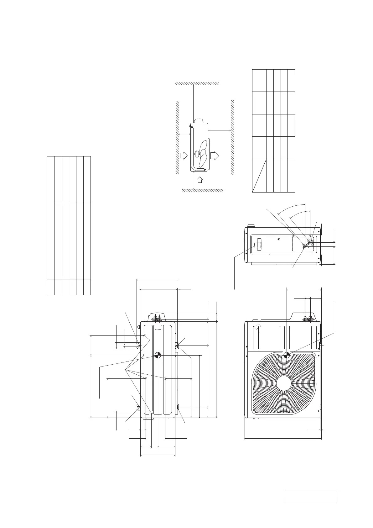
φ9.52(3/8")(Flare)
Content
C Pipe/cable draw-out hole
D
E Anchor bolt hole
Drain discharge hole
Symbol
B
A Service valve connection(Gas side)
M10-12×4 places
φ20×5 places
Service valve connection(Liquid side)
φ6.35(1/4")(Flare)
Unit:mm
145
520
290
2-R
2-12X16
Slot hole
L2
Inlet
Outlet
Inlet
L3
L1
Service
space
( )
L4
Terminal block
L2
L3
L4
L1
100
100
250
Open
I Ⅱ
Open
250
80
280
Ⅲ
280
Open
80
75
Examples
Size
installation
Ⅳ
180
Open
80
Open
Minimum installation space
A
C
B
D E
E
E
E
93 42.5
640
800
89 510 201
327.3
83.5
290
43.5
327.3
50.6
12
312.514.8
71.2
17.9
40°
40°
33.5148.4
12.4
351.6
38.6
90.6
520.6 161
35.6
Notes
(1) The unit must not be surrounded by walls on the four sides.
(2) The unit must be fixed with anchor bolts. An anchor bolt must not
protrude more than 15mm.
(3) If the unit is installed in the location where there is a possibility of
strong winds, place the unit such that the direction of air from the
outlet gets perpendicular to the wind direction.
(4) Leave 200mm or more space above the unit.
(5) The wall height on the outlet side should be 1200mm or less.
(6) The model name label is attached on the right side of the unit.
Center of gravity
Center of gravity
(2) Outdoor units
Models SRC20ZSX-W, 25ZSX-W, 35ZSX-W
RCT000Z025
 Loading...