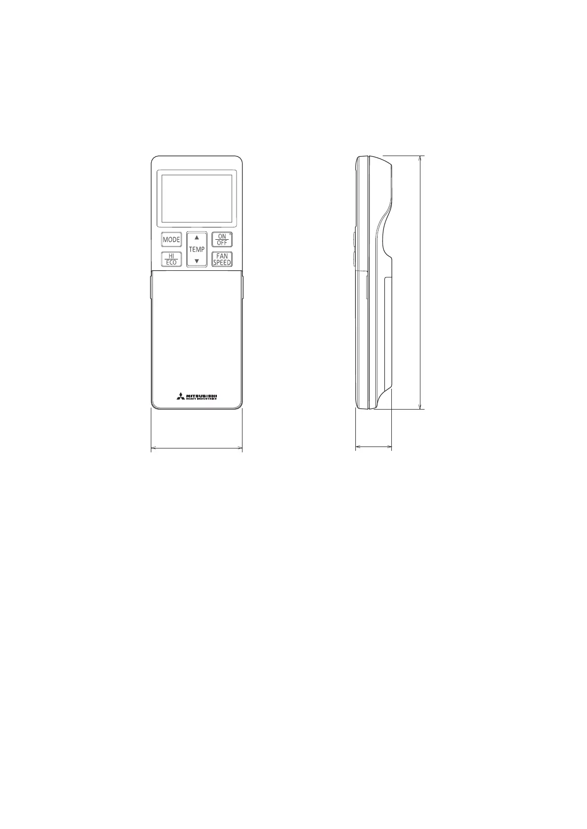
Unit:mm
145
520
290
2-12X16
Slot hole
2-R
L2
Inlet
Outlet
Inlet
L3
L1
Service
space
( )
L4
Terminal block
L2
L3
L4
L1
100
100
250
Open
Ⅰ
Ⅱ
Open
250
80
280
Ⅲ
280
Open
80
75
Ⅳ
180
Open
80
Open
Examples
Size
installation
Minimum installation space
A
C
B
D
E
E
E
E
93 42.5
640
800
89 510 201
327.3
83.5
290
43.5
327.3
50.6
12
312.514.8
71.2
17.9
40°
40°
33.5148.4
12.4
351.6
90.6
520.6 161
35.6
38.6
16.4
Notes
(1) The unit must not be surrounded by walls on the four sides.
( 2) The unit must be fixed with anchor bolts. An anchor bolt must not
protrude more than 15mm.
( 3) If the unit is installed in the location where there is a possibility of
strong winds, place the unit such that the direction of air from the
outlet gets perpendicular to the wind direction.
( 4) Leave 200mm or more space above the unit.
( 5) The wall height on the outlet side should be 1200mm or less.
( 6) The model name label is attached on the front side of the unit.
Center of gravity
Center of gravity
Content
C Pipe/cable draw-out hole
D
E Anchor bolt hole
Drain discharge hole
Symbol
B
A Service valve connection(gas side)
Service valve connection(liquid side)
φ12.7(1/2")( Flare)
M10-12×4 places
φ20×5 places
φ6.35(1/4")( Flare)
 Loading...