-
56
-
(2) Installation of outoor unit
C
• This installation manual deals with an outdoor unit installation only. For an indoor unit installation, refer to page 52.
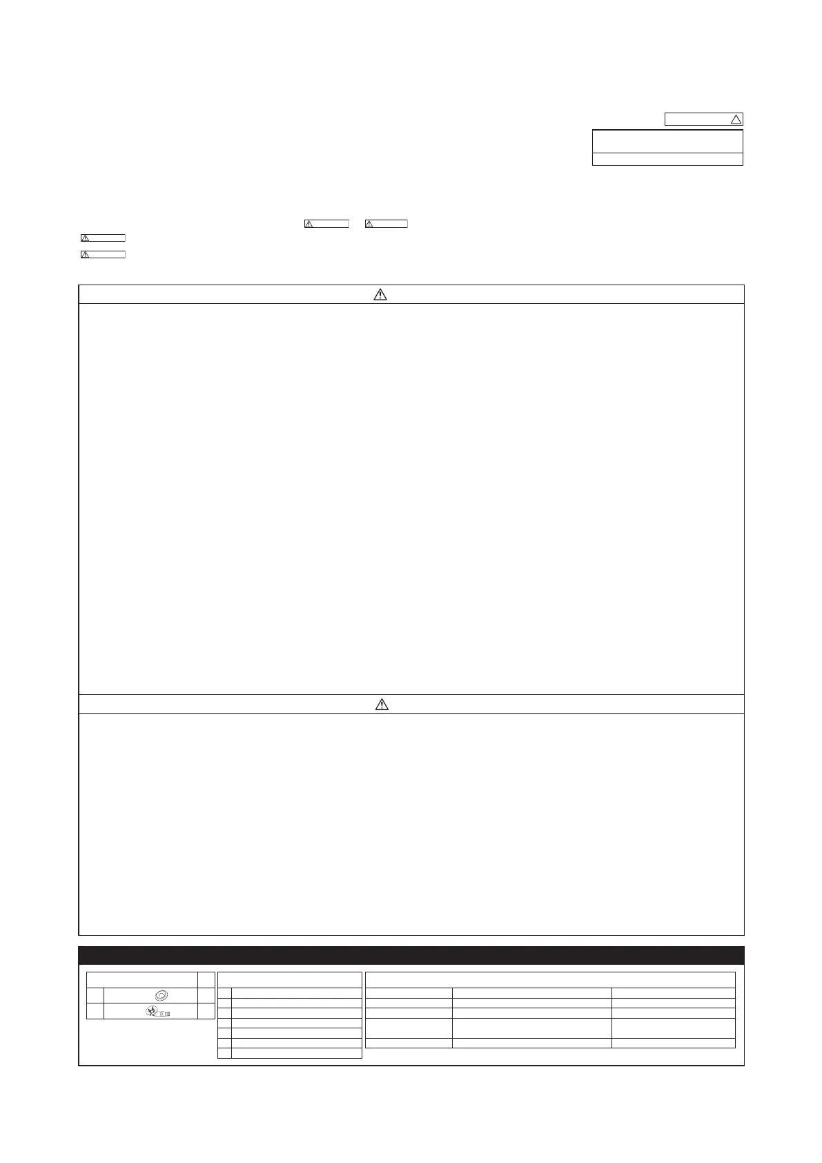
SAFETY PRECAUTIONS
• Before installation, read the “SAFETY PRECAUTIONS” carefully and strictly follow it during the installa-
tion work in order to protect yourself.
• The precautionary items mentioned below are distinguished into two levels,
and
.
Indicates a potentially hazardous situation which, if not avoided, can result in serious con-
sequences such as death or severe injury.
Indicates a potentially hazardous situation which, if not avoided, can result in personal in-
jury or property damage.
Both mention the important items to protect your health and safety. Therefore, strictly follow them by any means.
• Be sure to con rm no operation problem on the equipment after completing the installation. If unusual
noise can be heard during the test run, consult the dealer.
• Be sure to explain the operating methods as well as the maintenance methods of this equipment to the
user according to the user’s manual.
• Be sure to keep the installation manual together with user’s manual at a place where it is easily accessi-
ble to the user any time. Moreover, ask the user to hand the manuals to a new user, whenever required.
WARNING
• Be sure to use only for residential purpose.
If this unit is installed in inferior environment such as machine shop, vehicle (like ship), warehouse,
etc., it can malfunction.
• Installation must be carried out by the qualifi ed installer completely in accor-
dance with the installation manual.
Installation by non qualifi ed person or incorrect installation can cause serious troubles such as water
leak, electric shock, fi re and personal injury.
•
Be sure to wear protective goggles and gloves while performing installation work.
Improper safety measures can result in personal injury.
• Use the original accessories and the specifi ed components for the installation.
Using parts other than those prescribed may cause water leak, electric shock, fi re and personal injury.
•
Do not install the unit near the location where leakage of ammable gases can occur.
If leaked gases accumulate around the unit, it can cause fi re resulting in property damage and per-
sonal injury.
• When installing the unit in small rooms, make sure that refrigerant density
does not exceed the limit (Reference: ISO5149) in the event of leakage.
If refrigerant density exceeds the limit, consult the dealer and install the ventilation system.
Otherwise lack of oxygen can occur resulting in serious accident.
• Install the unit in a location where unit will remain stable, horizontal and free
of any vibration transmission.
Unsuitable installation location can cause the unit to fall resulting in material damage and personal injury.
• Do not run the unit with removed panels or protections.
Touching rotating equipments, hot surfaces or high voltage parts can cause personal injury due to
entrapment, burn or electric shock.
• This unit is designed specifi cally for R32.
Using any other refrigerant can cause unit failure and personal injury.
• Do not vent R32 into atmosphere.
R32 is a fl uorinated greenhouse gas with a Global Warming Potential(GWP)=675.
• Make sure that no air enters the refrigerant circuit when the unit is installed
and removed.
If air enters the refrigerant circuit, the pressure in the refrigerant circuit will become too high, which
can cause burst and personal injury.
• Be sure to use the prescribed pipes, are nuts and tools for R32 or R410A.
Using existing parts (for R22 or R407C) can cause refrigerant circuit burst resulting in unit failure and
personal injury.
• Be sure to connect both liquid and gas connecting pipes properly before op-
erating the compressor.
Do not open the liquid and gas operation valves before completing piping
work, and evacuation.
If the compressor is operated when connecting pipes are not connected and operation valves are
open, air can be sucked into the refrigerant circuit which can cause anomalous high pressure result-
ing in burst or personal injury.
• Be sure to tighten the are nuts to specifi ed torque using the torque wrench.
Tightening fl are nuts with excess torque can cause burst and refrigerant leakage after a long period.
• During pump down work, be sure to stop the compressor before closing ser-
vice valves and removing connecting pipes.
If the connecting pipes are removed when the compressor is in operation and service valves are
open, air can be sucked into the refrigerant circuit which can cause anomalous high pressure result-
ing in burst or personal injury.
• In the event of refrigerant leakage during installation, be sure to ventilate the
working area properly.
If the refrigerant comes into contact with naked fl ames, poisonous gases will be produced.
• Electrical work must be carried out by the qualifi ed electrician, strictly in ac-
cordance with national or regional electricity regulations.
Incorrect installation can cause electric shock, fi re or personal injury.
• Make sure that earth leakage breaker and circuit breaker of appropriate ca-
pacities are installed.
Circuit breaker should be able to disconnect all poles under over current. Absence of appropriate
breakers can cause electric shock, personal injury or property damage.
• Be sure to switch off the power source in the event of installation, mainte-
nance or service.
If the power source is not switched off, there is a risk of electric shock, unit failure or personal injury.
• Be sure to tighten the cables securely in terminal block and relieve the ca-
bles properly to prevent overloading the terminal blocks.
Loose connections or cable mountings can cause anomalous heat production or fi re.
• Do not process, splice or modify the power cable, or share the socket with
other power plugs.
Improper power cable or power plug can cause fi re or electric shock due to poor connection, insuf-
fi cient insulation or over-current.
• Do not perform any change in protective device or its setup condition yourself.
Changing protective device specifi cations can cause electric shock, fi re or burst.
• Be sure to clamp the cables properly so that they do not touch any internal
component of the unit.
If cables touch any internal component, it can cause overheating and fi re.
• Be sure to install service cover properly.
Improper installation can cause electric shock or fi re due to intrusion of dust or water.
• Be sure to use the prescribed power and connecting cables for electrical work.
Using improper cables can cause electric leak or fi re.
• This appliance must be connected to main power source by means of a cir-
cuit breaker or switch with a contact separation of at least 3mm.
Improper electrical work can cause unit failure or personal injury.
•
When plugging this unit, a plug conforming to the standard IEC60884-1 must be
used.
Using improper plug can cause electric shock or fi re.
• Be sure to connect the power source cable with power source properly.
Improper connection can cause intrusion of dust or water resulting in electric shock or fi re.
CAUTION
• Take care when carrying the unit by hand.
If the unit weight is more than 20kg, it must be carried by two or more persons.
Do not carry the unit by the plastic straps. Always use the carry handle.
• Do not install the outdoor unit in a location where insects and small animals
can inhabit.
Insects and small animals can enter the electrical parts and cause damage resulting in fi re or per-
sonal injury. Instruct the user to keep the surroundings clean.
• If the outdoor unit is installed at height, make sure that there is enough space
for installation, maintenance and service.
Insuffi cient space can result in personal injury due to falling from the height.
• Do not install the unit near the location where neighbours are bothered by
noise or air generating from the unit.
It can affect surrounding environment and cause a claim.
• Do not install in the locations where unit is directly exposed to corrosive
gases (like sulphide gas, chloride gas), sea breeze or salty atmosphere.
It can cause corrosion of heat exchanger and damage to plastic parts.
• Do not install the unit close to the equipments that generate electromagnetic
waves and/or high-harmonic waves.
Equipment such as inverters, standby generators, medical high frequency equipments and telecom-
munication equipments can affect the system, and cause malfunctions and breakdowns.
The system can also affect medical equipment and telecommunication equipment, and obstruct its
function or cause jamming.
• Do not install the unit in the locations where:
• There are heat sources nearby.
• Unit is directly exposed to rain or sunlight.
• There is any obstacle which can prevent smooth air circulation from inlet and outlet side of the unit.
• Unit is directly exposed to oil mist and steam such as kitchen.
• Chemical substances like ammonia (organic fertilizer), calcium chloride (snow melting agent) and
acid (sulfurous acid etc.), which can harm the unit, will generate or accumulate.
• Drain water can not be discharged properly.
• TV set or radio receiver is placed within 1m.
• Height above sea level is more than 1000m.
It can cause performance degradation, corrosion and damage of components, unit malfunction and fi re.
• Dispose of all packing materials properly.
Packing materials contain nails and wood which can cause personal injury.
Keep the polybag away from children to avoid the risk of suffocation.
• Do not put anything on the outdoor unit.
Object may fall causing property damage or personal injury.
• Do not touch the aluminum fi n of the outdoor unit.
Aluminium fi n temperature is high during heating operation. Touching fi n can cause burn.
•
Do not touch any refrigerant pipe with your hands when the system is in operation.
During operation the refrigerant pipes become extremely hot or extremely cold depending on the op-
erating condition. Touching pipes can cause personal injury like burn (hot/cold).
• Install isolator or disconnect switch on the power source wiring in accor-
dance with the local codes and regulations.
The isolator should be locked in OFF state in accordance with EN60204-1.
2. OUTDOOR UNIT INSTALLATION
Note as a unit designed for R32
• Do not use any refrigerant other than R32. R32 will rise to pressure about 1.6 times higher than that of
a conventional refrigerant. A cylinder containing R32 has a light blue indication mark on the top.
• Do not use a charge cylinder. The use of a charge cylinder will cause the refrigerant composition to
change, which results in performance degradation.
• In charging refrigerant, always take it out from a cylinder in the liquid phase.
• All indoor units must be models designed exclusively for R32. Check connectable indoor unit models in
a catalog, etc. (A wrong indoor unit, if connected into the system, will impair proper system operation)
1. Haulage
• Always carry or move the unit with two or more persons.
• The right hand side of the unit as viewed from the front (outlet
side) is heavier.
A person carrying the right hand side must take care of this fact.
A person carrying the left hand side must hold the handle pro-
vided on the front panel of the unit with his right hand and the
corner column section of the unit with his left hand.
CAUTION
When a unit is hauled, take care of its gravity center position which is shifted towards right hand side.
If the unit is not hauled properly, it can go off balance and fall resulting in serious injury.
2. Selecting the installation location
Select the suitable installation location where:
• Unit will be stable, horizontal and free of any vibration transmission.
• There is no obstacle which can prevent smooth air circulation from inlet and outlet side of the unit.
• There is enough space for service and maintenance of unit.
• Neighbours are not bothered by noise or air generating from the unit.
• Outlet air of the unit does not blow directly to animals or plants.
• Drain water can be discharged properly.
• There is no risk of ammable gas leakage.
• There are no other heat sources nearby.
• Unit is not directly exposed to rain or sunlight.
• Unit is not directly exposed to oil mist and steam.
• Chemical substances like ammonia (organic fertilizer), calcium chloride (snow melting agent) and acid
(sulfurous acid etc.), which can harm the unit, will not generate or accumulate.
• Unit is not directly exposed to corrosive gases (like sulphide gas, chloride gas), sea breeze or salty at-
mosphere.
• No TV set or radio receiver is placed within 1m.
• Unit is not affected by electromagnetic waves and/or high-harmonic waves generated by other equip-
ments.
• Strong wind does not blow against the unit outlet.
• Heavy snowfalls do not occur (If installed, provide proper protection to avoid snow accumulation).
NOTE
If the unit is installed in the area where there is a possibility of strong wind or snow accumulation, the fol-
lowing measures are required.
(1) Location of strong wind
• Place the unit with its outlet side facing the wall. • Place the unit such that the direction of air from
the outlet gets perpendicular to the wind direc-
tion.
Wind
direction
Wind
direction
(2) Location of snow accumulation
• Install the unit on the base so that the bottom is
higher than snow cover surface.
• Install the unit under eaves or provide the roof on
site.
3. Installation space
• There must be 1 meter or larger space between the unit and the wall in at least 1 of the 4 sides.
Walls surrounding the unit from 4 sides is not acceptable. The wall height on the outlet side should
be 1200 mm or less. Refer to the following gure and table for details.
(mm)
NOTE
When more than one unit are installed side by side, provide a 250mm or wider interval between them
as a service space.
CAUTION
When more than one unit are installed in parallel directions, provide suf cient inlet space so that short-
circuiting may not occur.
4. Drain piping work (If necessary)
Carry out drain piping work by using a drain elbow and a drain grommet supplied separately as acces-
sories if condensed water needs to be drained out.
(1) Install drain elbow and drain grommet.
(2) Seal around the drain elbow and drain grommet with putty or adequate caulking material.
<SRC20/25/35/40/50/60ZSX-W>
Do not put a grommet on this hole.
This is a supplementary drain hole to discharge
drain water, when a large amount of it is gathered.
CAUTION
Do not use drain elbow and drain grommet if there
is a possibility to have several consecutive days
of sub zero temperature. (There is a risk of drain
water freezing inside and blocking the drain.)
<SRC20/25/35ZSX-WA>
Do not block the drain holes when installing the
outdoor unit.
5. Installation
• Install the unit on a at level base.
• While installing the unit, keep space and x the unit’s legs with 4 anchor bolts as shown in the gure
below. The protrusion of an anchor bolt from the foundation surface must be kept within 15mm.
313 mm
15 mm
Anchor bolt (M10-12) ×4 pcs
200 mm over
If drain piping work was carried
out, keep the clearance more
than 100mm.
510 mm
CAUTION
•
Install the unit properly so that it does not fall over during earthquake, strong wind, etc.
•
Make sure that unit is installed on a at level base. Installing unit on uneven base may result in unit
malfunction.
3. PREPARATION FOR WORK
1. Removing service cover
Remove the screw. Slide service cover downwards and remove it.
2. Removing terminal cover
Remove the screw and take out terminal cover.
Heavy
RWC012A063B
Model SRC20,25,35,40,50,60ZSX-W
SRC20,25,35ZSX-WA
R32 REFRIGERANT USED
1. ACCESSORIES AND TOOLS
Locally procured parts Tools for installation work
(a) Anchor bolt(M10-M12)×4 pcs Plus headed driver Spanner wrench Vacuum pump*
(b) Putty Knife Torque wrench [14.0-62.0N•m(1.4-6.2kgf•m)] Gauge manifold *
(c) Electrical tape Saw Wrench key (Hexagon) [4mm] Charge hose *
*
Not included for SRC20, 25, or 35ZSX-WA
.
(d) Connecting pipe
Tape measure Flaring tool set *
Vacuum pump adapter*
(Anti-reverse ow type)
(e) Connecting cable
(f) Power cable Pipe cutter Flare adjustment gauge Gas leak detector *
(g) Clamp and screw (for nishing work)
*
Designed speci cally for R32 or R410A
Standard accessories
(Supplied with outdoor unit)
Q’ty
(1)
Drain grommet
4
(2)
Drain elbow
1
Example installation
I II III IV
Size
L1 Open 280 280 180
L2 100 75 Open Open
L3 100 80 80 80
L4 250 Open 250 Open
Inlet
(
Service
space
)
Inlet
Outlet
L3
L4
L1
L2
 Loading...