-
52
-
2. SELECTING INSTALLATION LOCATION
After getting customer’s approval, select installation location according to following guidelines.
1. Indoor unit
•
evenly distributed.
• A solid place where the unit or the wall will not vibrate.
• A place where there will be enough space for servicing.
(Where space mentioned on the right side can be secured.)
• Where it is easy to conduct wiring and piping work.
• A place where unit is not directly exposed to sunlight or street light.
• A place where it can be easily drained.
• A place separated at least 1m away from the television or the radio.
(To prevent interference to images and sounds.)
• A place where this unit is not affected by the high frequency equipment or electric equipment.
• Avoid installing this unit in place where there is much oil mist.
• A place where there is no electric equipment or household.
•
more than 180 cm.
2. Wireless remote control
• A place where the air-conditioner can receive the signal surely during operating the wireless
remote control.
• A place where it is not affected by the TV, radio etc.
• Do not place where it is exposed to direct sunlight or near heat devices such as a stove.
Wireless remote control
Remote control holder
Wood screws
10 cm minimum
from the wall
10 cm minimum
from the wall
Installation board
6.5 cm minimum from the ceiling
(In the case of less than 10 cm,
there is a possibility of performance
degradation.)
(a) Sleeve
180 cm minimum from the floor
Installation example
Indoor
unit
Obstacle such
as curtain
11 cm 12 cm
Be sure that the
flap of outlet
should not
touch any
obstacles.
2 cm
Flap removal
position
Maximum
moving range
3. INSTALLING INSTALLATION BOARD
• Installation board should be installed on the wall which can support the weight of the indoor unit.
• Adjustment of the installation board in the horizontal direction is to be conducted with 5 screws in a
temporary tightened state.
• With the standard hole as a center, adjust the board and level it.
Standard
Mating mark for level surface
In case of fixing the unit on
concrete wall, use nut anchor.
CAUTION
Improper adjustment of the installation board can cause water leakage.
118.5118.5 683
145 630 145
568176
460 460
48.6
47
47
10.3
277.317.4
120
65
70
65
100
100
176
88.6
76.6
56.4
480 (Gas pipe)
Unit: mm
533 (Drain hose)
548 (Liquid pipe)
(Service Space)
4. DRILLING HOLE AND FIXTURE OF SLEEVE
When drilling the wall that contains a metal lath, wire lath or metal plate, be sure to use sealing plate, sleeve and inclination plate (Locally procured parts).
5
ø65
Indoor side Outdoor side
(a) Sleeve
Top
Thickness of the wall + 1.5cm
Cut
Indoor side Outdoor side Installed state
Turn to
tighten
(b) Sealing plate
(a) Sleeve
(1) Drill a hole with hole
core drill.
5. ELECTRICAL WIRING WORK
• Before installation, make sure that the power source complies w
• Carry out electrical wiring work according to following guidelines.
1. Preparing cable
(1) Selecting cable
.
4-core* 1.5mm
2
conformed with 60245 IEC57
* 1 Earth wire is included (Yellow/Green).
(2) Arrange each wire length as shown below.
Make sure that each wire is stripped 10mm from the end.
<Connecting cable> <Wire end>
40mm or more
(3) Attach round crimp-type terminal to each wire as shown in the below.
and wire diameter.
10mm
Round crimp-type terminal
Sleeve
2. Remove bottom panel
(1) Remove the 3 screws (in the cap).
(2) Remove the hooks of left and right side
and then bottom panel can be removed.
NOTE
•
• When opening the cap, exercise care not to
damage the design surface.
3. Connecting cable
(1) Remove the terminal cover.
(2) Remove the cable clamp.
(3) Connect the connecting wires to the terminal block.
(4) Fix the connecting cable by cable clamp.
(5) Fix the terminal cover.
NOTE
Take care not to confuse the terminal numbers for indoor and outdoor connections.
Cable clamp
Terminal block
• Earth wire shall be Yellow/Green (Y/G) in color and
longer than other wires for safety reason.
Terminal cover
The screw of the terminal
cover is tightened securely
•
This installation manual deals with an indoor unit installation only. For an outdoor unit installation, refer to page 56.
•
This unit is designed for R32 or R410A. See a label on the outdoor unit to check refrigerant information.
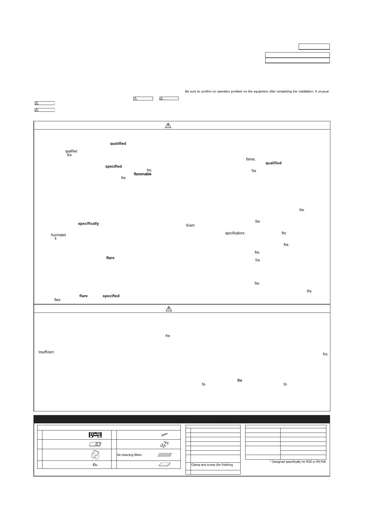
SAFETY PRECAUTIONS
• Before installation, read the “SAFETY PRECAUTIONS” carefully and strictly follow it during the installa-
tion work in order to protect yourself.
•
The precautionary items mentioned below are distinguished into two levels,
and
.
Indicates a potentially hazardous situation which, if not avoided, can result in serious con-
sequences such as death or severe injury.
Indicates a potentially hazardous situation which, if not avoided, can result in personal in-
jury or property damage.
Both mention the important items to protect your health and safety. Therefore, strictly follow them by any means.
•
noise can be heard during the test run, consult the dealer.
• Be sure to explain the operating methods as well as the maintenance methods of this equipment to the
user according to the user’s manual.
• Be sure to keep the installation manual together with user’s manual at a place where it is easily accessi-
ble to the user any time. Moreover, ask the user to hand the manuals to a new user, whenever required.
WARNING
• Be sure to use only for residential purpose.
If this unit is installed in inferior environment such as machine shop, vehicle (like ship), warehouse,
etc., it can malfunction.
• Installation must be carried out by the
installer completely in accor-
dance with the installation manual.
Installation by non
person or incorrect installation can cause serious troubles such as water
leak, electric shock,
and personal injury.
•
Be sure to wear protective goggles and gloves while performing installation work.
Improper safety measures can result in personal injury.
• Use the original accessories and the
components for the installation.
Using parts other than those prescribed may cause water leak, electric shock, and personal injury.
•
Do not install the unit near the location where leakage of gases can occur.
If leaked gases accumulate around the unit, it can cause resulting in property damage and per-
sonal injury.
• When installing the unit in small rooms, make sure that refrigerant density
does not exceed the limit (Reference: ISO5149) in the event of leakage.
If refrigerant density exceeds the limit, consult the dealer and install the ventilation system.
Otherwise lack of oxygen can occur resulting in serious accident.
• Install the unit in a location where unit will remain stable, horizontal and free
of any vibration transmission.
Unsuitable installation location can cause the unit to fall resulting in material damage and personal injury.
• Do not run the unit with removed panels or protections.
Touching rotating equipments, hot surfaces or high voltage parts can cause personal injury due to
entrapment, burn or electric shock.
• This unit is designed
for R32 or R410A.
Using any other refrigerant can cause unit failure and personal injury.
• Do not vent R32 or R410A into atmosphere.
R32 is a
greenhouse gas with a Global Warming Potential(GWP)=675.
R410A is a
uorinated greenhouse gas with a Global Warming Potential(GWP)=2088.
• Make sure that no air enters the refrigerant circuit when the unit is installed
and removed.
If air enters the refrigerant circuit, the pressure in the refrigerant circuit will become too high, which
can cause burst and personal injury.
• Be sure to use the prescribed pipes,
nuts and tools for R32 or R410A.
Using existing parts (for R22 or R407C) can cause refrigerant circuit burst resulting in unit failure and
personal injury.
• Be sure to connect both liquid and gas connecting pipes properly before op-
erating the compressor.
Do not open the liquid and gas service valves before completing piping work,
and evacuation.
If the compressor is operated when connecting pipes are not connected and service valves are open,
air can be sucked into the refrigerant circuit which can cause anomalous high pressure resulting in
burst or personal injury.
• Be sure to tighten the
nuts to torque using the torque wrench.
Tightening
nuts with excess torque can cause burst and refrigerant leakage after a long period.
• During pump down work, be sure to stop the compressor before closing ser-
vice valves and removing connecting pipes.
If the connecting pipes are removed when the compressor is in operation and service valves are
open, air can be sucked into the refrigerant circuit which can cause anomalous high pressure result-
ing in burst or personal injury.
• In the event of refrigerant leakage during installation, be sure to ventilate the
working area properly.
If the refrigerant comes into contact with naked poisonous gases will be produced.
• Electrical work must be carried out by the electrician, strictly in ac-
cordance with national or regional electricity regulations.
Incorrect installation can cause electric shock, or personal injury.
• Make sure that earth leakage breaker and circuit breaker of appropriate ca-
pacities are installed.
Circuit breaker should be able to disconnect all poles under over current. Absence of appropriate
breakers can cause electric shock, personal injury or property damage.
• Be sure to switch off the power source in the event of installation, mainte-
nance or service.
If the power source is not switched off, there is a risk of electric shock, unit failure or personal injury.
• Be sure to tighten the cables securely in terminal block and relieve the ca-
bles properly to prevent overloading the terminal blocks.
Loose connections or cable mountings can cause anomalous heat production or
• Do not process, splice or modify the power cable, or share the socket with
other power plugs.
Improper power cable or power plug can cause or electric shock due to poor connection, insuf-
insulation or over-current.
• Do not perform any change in protective device or its setup condition yourself.
Changing protective device can cause electric shock, or burst.
• Be sure to clamp the cables properly so that they do not touch any internal
component of the unit.
If cables touch any internal component, it can cause overheating and
• Be sure to install service cover properly.
Improper installation can cause electric shock or due to intrusion of dust or water.
• Be sure to use the prescribed power and connecting cables for electrical work.
Using improper cables can cause electric leak or
• This appliance must be connected to main power source by means of a cir-
cuit breaker or switch with a contact separation of at least 3mm.
Improper electrical work can cause unit failure or personal injury.
•
When plugging this unit, a plug conforming to the standard IEC60884-1 must be
used.
Using improper plug can cause electric shock or
• Be sure to connect the power source cable with power source properly.
Improper connection can cause intrusion of dust or water resulting in electric shock or
CAUTION
• Take care when carrying the unit by hand.
If the unit weight is more than 20kg, it must be carried by two or more persons.
Do not carry the unit by the plastic straps. Always use the carry handle.
• Do not install the outdoor unit in a location where insects and small animals
can inhabit.
Insects and small animals can enter the electrical parts and cause damage resulting in or per-
sonal injury. Instruct the user to keep the surroundings clean.
• If the outdoor unit is installed at height, make sure that there is enough space
for installation, maintenance and service.
space can result in personal injury due to falling from the height.
• Do not install the unit near the location where neighbours are bothered by
noise or air generating from the unit.
It can affect surrounding environment and cause a claim.
• Do not install in the locations where unit is directly exposed to corrosive
gases (like sulphide gas, chloride gas), sea breeze or salty atmosphere.
It can cause corrosion of heat exchanger and damage to plastic parts.
• Do not install the unit close to the equipments that generate electromagnetic
waves and/or high-harmonic waves.
Equipment such as inverters, standby generators, medical high frequency equipments and telecom-
munication equipments can affect the system, and cause malfunctions and breakdowns.
The system can also affect medical equipment and telecommunication equipment, and obstruct its
function or cause jamming.
• Do not install the unit in the locations where:
• There are heat sources nearby.
• Unit is directly exposed to rain or sunlight.
• There is any obstacle which can prevent smooth air circulation from inlet and outlet side of the unit.
• Unit is directly exposed to oil mist and steam such as kitchen.
• Chemical substances like ammonia (organic fertilizer), calcium chloride (snow melting agent) and
acid (sulfurous acid etc.), which can harm the unit, will generate or accumulate.
• Drain water can not be discharged properly.
• TV set or radio receiver is placed within 1m.
• Height above sea level is more than 1000m.
It can cause performance degradation, corrosion and damage of components, unit malfunction and
• Dispose of all packing materials properly.
Packing materials contain nails and wood which can cause personal injury.
Keep the polybag away from children to avoid the risk of suffocation.
• Do not put anything on the outdoor unit.
Object may fall causing property damage or personal injury.
• Do not touch the aluminum of the outdoor unit.
Aluminium temperature is high during heating operation. Touching can cause burn.
•
Do not touch any refrigerant pipe with your hands when the system is in operation.
During operation the refrigerant pipes become extremely hot or extremely cold depending on the op-
erating condition. Touching pipes can cause personal injury like burn (hot/cold).
• Install isolator or disconnect switch on the power source wiring in accor-
dance with the local codes and regulations.
The isolator should be locked in OFF state in accordance with EN60204-1.
RLF012A202B
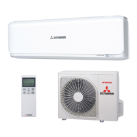
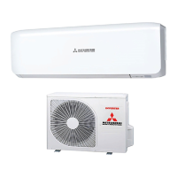
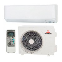
Model SRK20,25,35,50,60ZSX
R32/R410A REFRIGERANT USED
1. ACCESSORIES AND TOOLS
Standard accessories (Supplied with indoor unit)
(1) Installation board
1pc (5)
Wood screws
(for remote control holder ø3.5 X 16mm)
2pcs
(2) Wireless remote control
1pc (6)
Batteries [R03 (AAA, Micro) 1.5V]
2pcs
(3) Remote control holder
1pc (7) 2pcs
(4)
Tapping screws
(for installation board ø4 X 25mm)
5pcs (8) Insulation (#486 50 X 100 t3) 1pc
Locally procured parts
(a) Sleeve (1pc)
(b) Sealing plate (1pc)
(c) Inclination plate (1pc)
(d) Putty
(e) Connecting cable
(f) Drain hose (extension hose)
(g)
Piping cover
(for insulation of connection piping)
(h)
work)
(i) Electrical tape
Tools for installation work
Plus headed driver Pipe cutter
Knife
Hole core drill (65mm in diameter)
Saw Wrench key (Hexagon) [4mm]
Tape measure Flaring tool set*
Torque wrench
(14.0-62.0N·m (1.4-6.2kgf·m))
Gas leak detector*
Pipe bender
Plier Flare adjustment gauge
Bottom panel
Screw (in the cap)
CAUTION
Completely seal the hole in the wall with putty.
be damaged by water leakage or condensation.
WARNING
Completely seal the hole in the wall with putty.
If not sealed properly, dust, insects, small animals,
and highly humid air may enter the room from out-
(3) Fix sealing plate, sleeve
and inclination plate.
(2) Cut sleeve to adjust to wall
thickness. In case of rear
piping draw out, cut off the
lower and the right side
portions of the sleeve collar.
(4) After piping work,
seal the hole in the wall
with putty.
RLF012A202B_cc.indd 1 H29/09/21 20:19
8. APPLICATION DATA
(1) Installation of indoor unit
 Loading...