2-8 MAINTENANCE
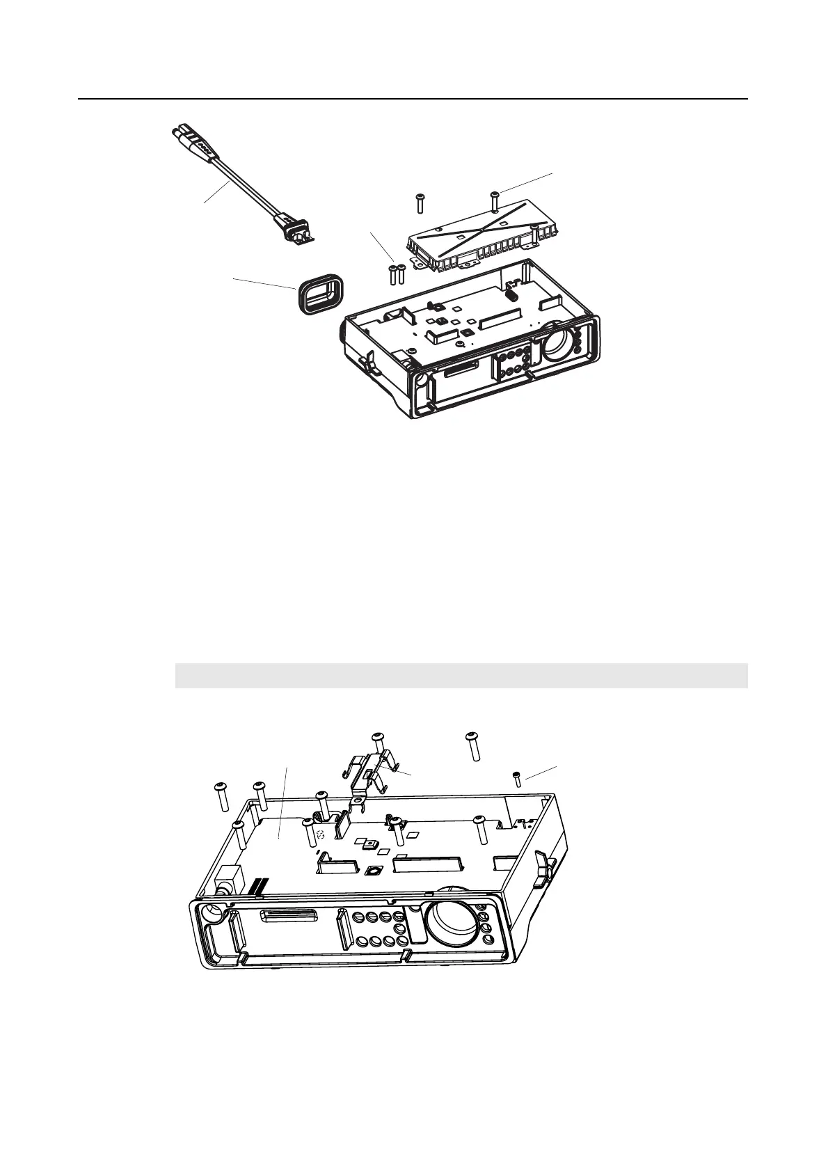
Figure 2-8 PA Shield and DC Cable Removal (for Radios without PA Clip)
6.5 Main PCB Removal
6.5.1 For Radios with PA Clip
1. Remove the screw that attaches the PA clip to the chassis. See Figure 2-9.
2. Remove the PA clip.
3. Remove all the screws that fix the PCB to the chassis.
4. Loosen the M2 screw (if fitted) on the RF connector, about 3 to 4 turns using Hex tool.
5. Loosening this screw, enables you to unscrew the RF connector from outside.
6. Carefully remove the main PCB in a diagonal manner.
Figure 2-9 PA Clip and Main PCB Removal
NOTE
It is recommended to grip the volume potentiometer and remove the PCB board
PA Shield
Fixing Screws (3)
DC
Cable
DC Cable
Fixing Screws
(2)
M2 Screw
PA Clip
Main PCB
Accessory
Connector
Cap
 Loading...