Radio Exploded Mechanical Views and Parts Lists 2-15
8.0 Radio Exploded Mechanical Views and Parts Lists
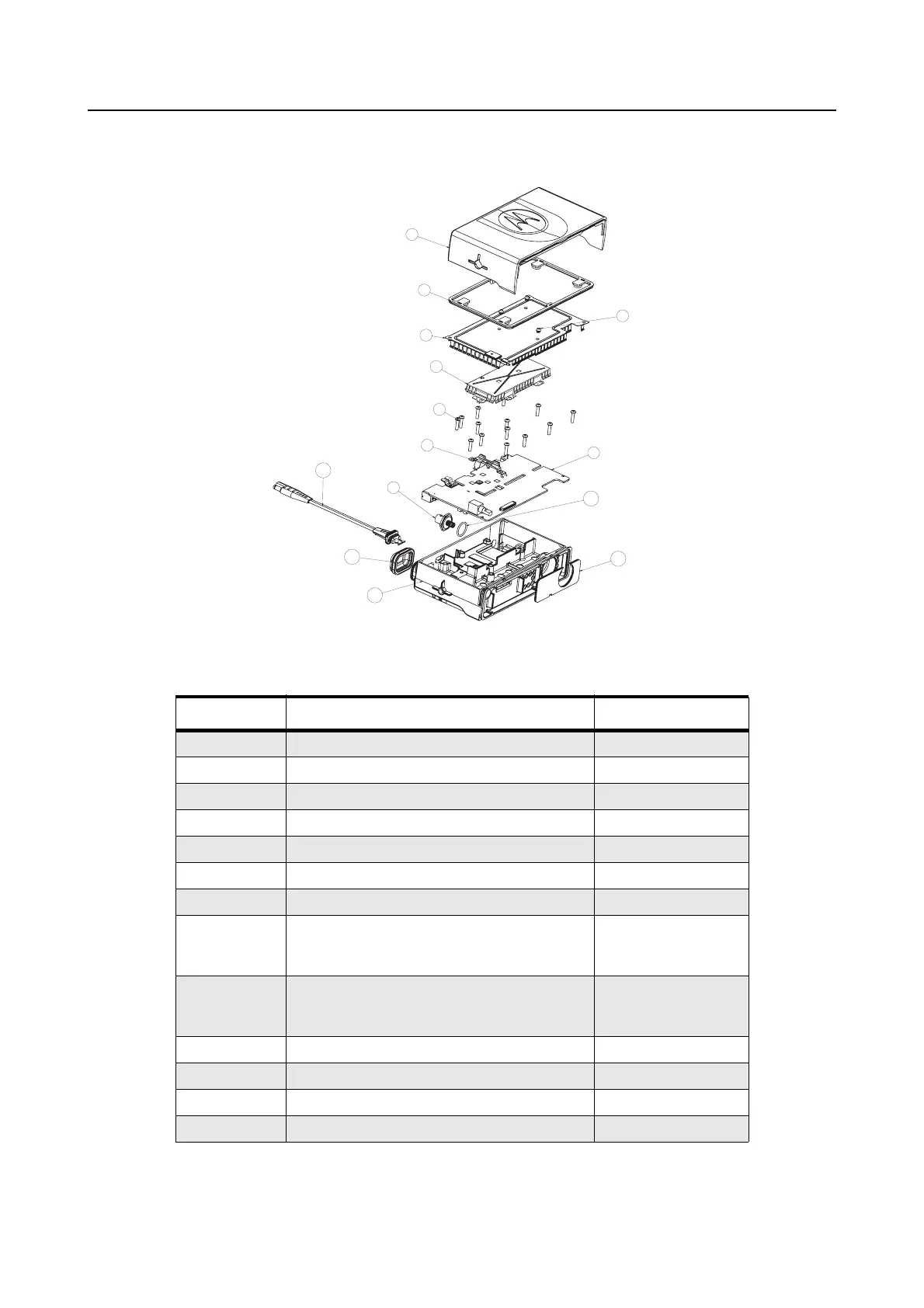
8.1 Radio Assembly - 25W Models (for Radios with PA Clip)
Figure 2-14 Radio Assembly - 25W Models
Table 2-1 Radio Assembly Parts List - 25W Models
Item No. Description Part Number
1 Upper Cover 1589224U01
2 Main Seal 3289329U01
3 Bumper 7587509V06
4 Main Shield 2689338U01
5 PA Shield 2689337U01
6 Screw 0310943J12
7 PA Clip 0789352U01
8 VHF Main PCB
UHF Main PCB
Midband Main PCB
FLD6000A
FLE6029A
FUC1600A
9 Connector Jack:
Mini UHF
BNC
5886750Z01
5886751Z01
10 Power Cable Assembly 0189484U01
11 Cap, Accessory Connector 3202607Y01
12 Chassis 25W 2789223U01
13 Felt 3586661Z01
1
2
3
4
5
6
7
8
9
9
10
11
13
12
 Loading...