EasyManuals Logo

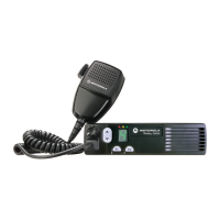
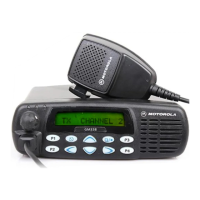
Motorola Radius CM300 User Manual

Motorola Radius CM300
314 pages
To Next Page IconTo Next Page
To Previous Page IconTo Previous Page
Page #258 background imageLoading...
Page #258 background image
3-8 TROUBLESHOOTING CHARTS
4.0 Troubleshooting Flow Chart for VCO
Are Q200
Base at 2.4V
Collector at 4.5V
Emitter at 1.7V
Are U201 Pins
13 at 4.4V
15 at 1.1V
10 at 4.5V
16 at 1.9V
Low or no RF Signal
at TP1
Visual check
of board
OK?
35mV DC at
U201 Pin 19
NO
YES
at base of Q200
NO
NO
NO
NO
YES
YES
YES
YES
Low or no RF Signal
at input to PA
3.3V DC at U201
Pin 14 & 18 OK?
4.8V DC at
U201 Pin 19
Is RF available
at C2060
YES
YES
YES
YES
YES
NO
NO
NO
NO
NO
Audio =180mVrms
at “+” side of
D205
2.5VDC
at D205
If R211 is Ok,
replace D205
Replace R211
Replace R212
NO
NO
YES
YES
TX VCO
RX VCO
Correct
Problem
Visual check
of board
OK?
Make sure U508 is working
correctly and runner
between U508 Pin 1 and
U201 Pin 14 & 18 is OK
Check runner
between U200 Pin 2
and U201 Pin 19
Is RF available
If all parts from U200 Pin 8
to Base of Q200 are OK,
replace U200
Check parts between
TP1 and Q200
Power OK but
no modulation
Check Transmiter
Pre Driver
If all parts
associated
with the pins
are OK,
replace U201
4.5V DC at
U201 Pin 3 OK?
YES
NO
4.5V DC at
U201 Pin 3 OK?
YES
NO
Make sure Synthesizer is
working correctly and runner
between U200 Pin 28 and
U201 Pin 3 is OK
3.3 DC at U201
Pin 14 & 18 OK?
OK?
OK?
If all parts associated
with the pins are OK
replace U201
If L216, C2071, C2070,
C2060 are okay
replace U201
Check 9V at R230
YES

Table of Contents

Other manuals for Motorola Radius CM300

Questions and Answers:

Question and Answer IconNeed help?

Do you have a question about the Motorola Radius CM300 and is the answer not in the manual?

Motorola Radius CM300 Specifications

General IconGeneral
BrandMotorola
ModelRadius CM300
CategoryRadio
LanguageEnglish

Related product manuals