2-4 THEORY OF OPERATION
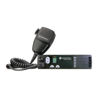
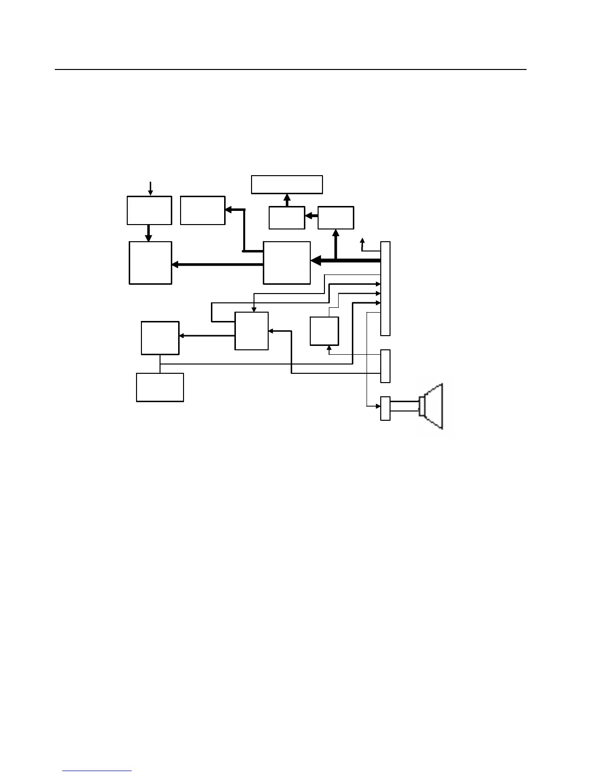
3.0 Control Head Model for CM300/PM400
The control head contains the internal speaker, the on/off/volume knob, the microphone connector,
several buttons to operate the radio, three indicator Light Emitting Diodes (LED) to inform the user
about the radio status, and an 8 character Liquid Crystal Display (LCD) for alpha-numerical
information e.g. channel number or call address name.
3.1 Power Supplies
The power supply to the control head is taken from the host radio’s 9.3V via connector J103-9, The
9.3V is used for the LEDs and back light, the 5V is used for the LCD driver (U3) and level shifter
(U4). The stabilized 3V is used for the other parts.
3.2 SPI Interface
The host radio (master) communicates with the control head through its SPI bus. Three lines are
connected to the shift register (U8):SPI clock (J103-17), SPI MOSI (J103-16), shift register chip
select (J103-15) and LCD driver chip select (J103-18).
When the host radio needs to send date to the shift register, the radio asserts the shift register chip
select and the data is loaded to the shift register. For example, the host radio sends data to change
display channel or change LED status.
8 pin JACK
connector
9.3V
LCD
Shift
Register
Backlight
Control
Mux.
Control
Keypads
Keypad
Resistors
PTT
circuit
2-pin speaker
connector
9.3V
LED
Indicators
Row/Column
Control line
Boot_Res / SCI
DTMF
Row/Column
Boot_Res (DTMF-
Column)/ SCI
(DTMF-Row)
Level
Shifter
LCD
Driver
LED
Backlight
8 pin JACK
connector
9.3V
LCD
Shift
Register
Backlight
Control
Mux.
Control
Keypads
Keypad
Resistors
PTT
circuit
2-pin speaker
connector
9.3V
LED
Indicators
Row/Column
Control line
Boot_Res / SCI
DTMF
Row/Column
Boot_Res (DTMF-
Column)/ SCI
(DTMF-Row)
Level
Shifter
LCD
Driver
LED
Backlight
 Loading...