Chapter 2
THEORY OF OPERATION
1.0 Introduction
This Chapter provides a detailed theory of operation for the Control head circuits. For details of the
trouble shooting refer to the related chapter in this section.
2.0 Control Head Model for CM200
The head contains the internal speaker, the on/off/volume knob, the microphone connector, several
buttons to operate the radio and three indicator Light Emitting Diodes (LED) to inform the user about
the radio status and a 7-segment display for numeric information.
2.1 Power Supplies
The power supply to the head is taken from the host radio’s 9.3V via connector J803-9, The 9.3V is
used for the LEDs and back light, the 5V is used for the LCD driver and level shifter. The stabilized
3V is used for the other parts.
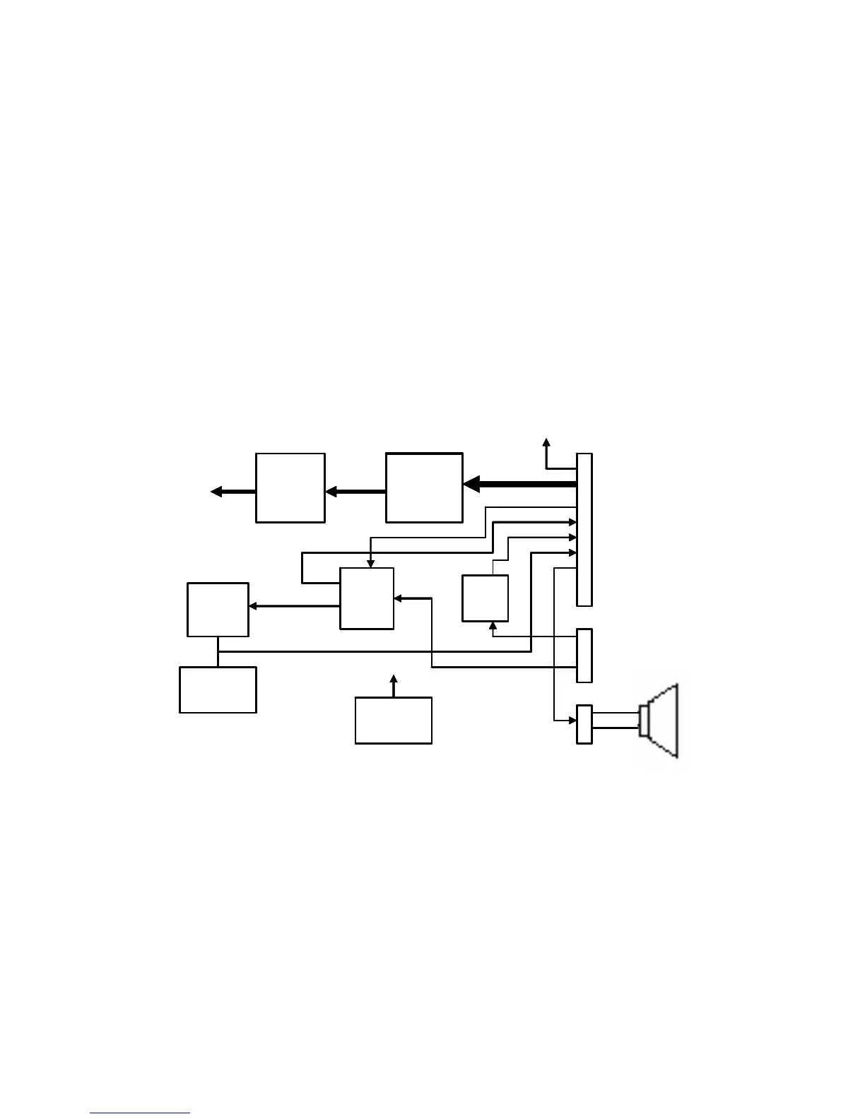
2.2 SPI Interface
The host radio (master) communicates with the head through its SPI bus. Three lines are
connected to the shift register (U801):SPI clock (J803-17), SPI MOSI (J803-16) and shift register
chip select (J803-15).
Shift
Register
BCD To
7-segment
Mux.
Control
Keypads
DTMF
Resistors
PTT
circuit
2 pin speaker
connector
7-segment
display
9.3V
Keypad
Backlight
9.3VRow/Column
Control line
Boot_res / SCI
DTMF
Row/Column
Boot_res (DTMF-
Column)/ SCI
(DTMF-Row)
Shift
Register
BCD To
7-segment
Mux.
Control
Keypads
DTMF
Resistors
PTT
circuit
2 pin speaker
connector
7-segment
display
9.3V
Keypad
Backlight
9.3VRow/Column
Control line
Boot_res / SCI
DTMF
Row/Column
Boot_res (DTMF-
Column)/ SCI
(DTMF-Row)
4
 Loading...