2-8 THEORY OF OPERATION
5.0 Controller Theory of Operation
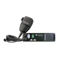
This section provides a detailed theory of operation for the radio and its components. The main
radio is a single-board design, consisting of the transmitter, receiver, and controller circuits. A
control head is connected by an extension cable. The control head contains LED indicators, a
microphone connector, buttons, and speaker.
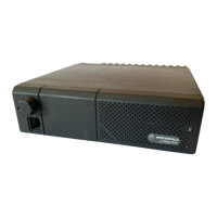
In addition to the power cable and antenna cable, an accessory cable can be attached to a
connector on the rear of the radio. The accessory cable enables you to connect accessories to the
radio, such as an external speaker, emergency switch, foot-operated PTT, and ignition sensing, etc.
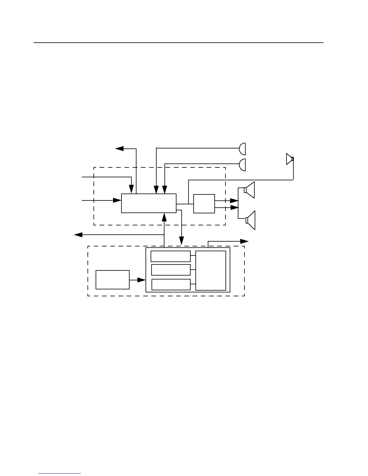
Figure 2-5 Controller Block Diagram
5.1 Radio Power Distribution
Voltage distribution is provided by five separate devices:
• U514 P-cH FET – Batt + (Ext_SWB+)
• U501 LM2941T – 9.3 V
• U503 LP2951CM – 5 V
• U508 MC 33269DTRK – 3.3 V
• U510 LP2986ILDX – 3.3 V Digital
External
Microphone
Internal
Microphone
External
Speaker
Internal
Speaker
SCI to
Control Head
Audio
PA
Audio/Signaling
Architecture
To Synthesizer
Mod
Out
16.8 MHz
Reference Clock
from Synthesizer
Disc Audio
To RF S e cti o n
SPI
Digital
Architecture
µP Clock
3.3 V
Regulator
RAM
EEPROM
FLASH
HC11FL0
ASFIC_CMP
Accessory &
Connector
Handset
.
 Loading...