2-15
Chapter 2 - Mainboard Hardware
1 2
JCOM1
9
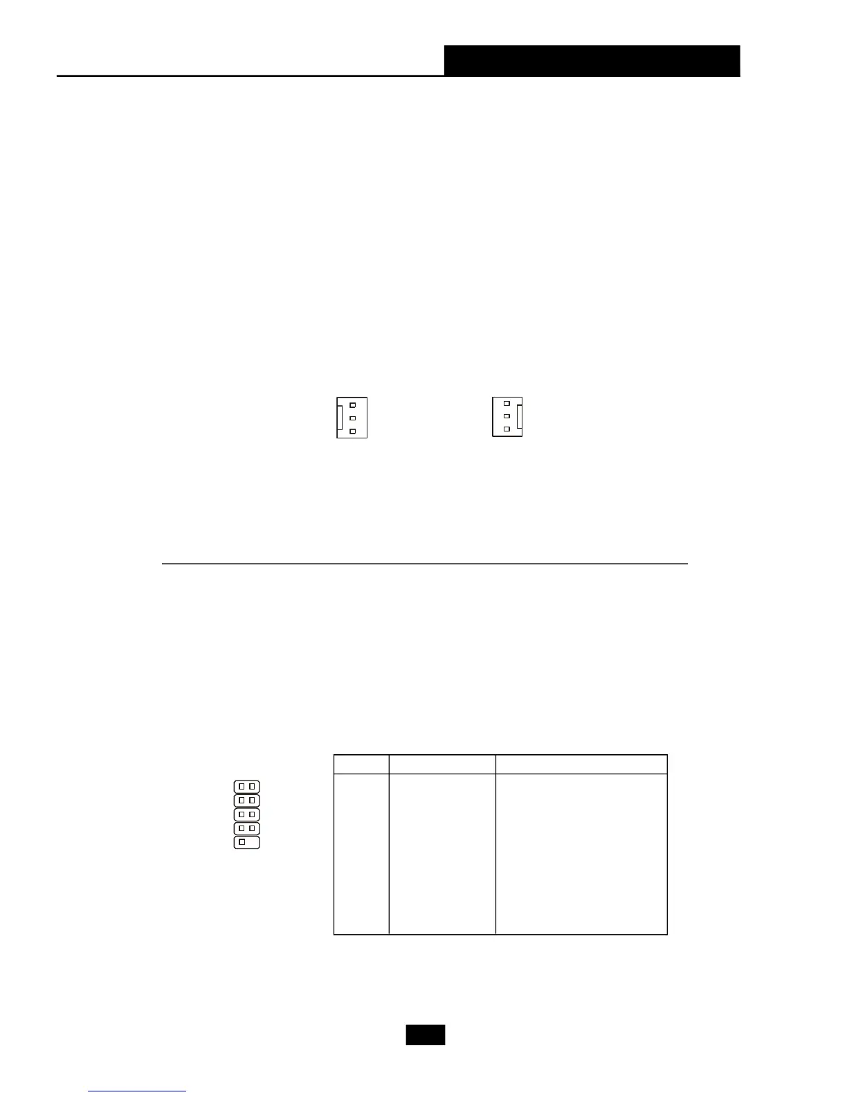
Fan Power Connectors: CPUFAN1/SFAN1
The CPUFAN1(processor fan) and SFAN1 (system fan) support system
cooling fan with +12V. It supports three-pin head connector. When connecting
the wire to the connectors, always take note that the red wire is the positive and
should be connected to the +12V, the black wire is Ground and should be
connected to GND. If the mainboard has a System Hardware Monitor chipset on-
board, you must use a specially designed fan with speed sensor to take advan-
tage of the CPU fan control.
SFAN1CPUFAN1
Sensor
+4.5V ~ +12V
GND
Sensor
+12V
GND
Serial Port Connector: JCOM1 (Optional)
The mainboard offers one serial port. It is 16550A high speed communi-
cation ports that senda/receivea/ 16 bytes FIFOs. You can attach a serial mouse
or other serial device directly to it.
PIN SIGNAL DESCRIPTION
1 DCD Data Carry Detect
2 SIN Serial In or Receive Data
3 SOUT Serial Out or Transmit Data
4 DTR Data Terminal Ready)
5 GND Ground
6 DSR Data Set Ready
7 RTS Request To Send
8 CTS Clear To Send
9 RI Ring Indicate
Pin Definition
 Loading...