EasyManuals Logo

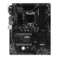
MSI Z170A SLI PLUS User Manual

MSI Z170A SLI PLUS
142 pages
To Next Page IconTo Next Page
To Previous Page IconTo Previous Page
Page #121 background imageLoading...
Page #121 background image
15
Компоненты материнской платы
JPWR1~2: Разъемы питания
Данные разъемы предназначены для подключения коннекторов питания ATX.
24
131
12
JPWR1
1 +3.3V 13 +3.3V
2 +3.3V 14 -12V
3 Ground 15 Ground
4 +5V 16 PS-ON#
5 Ground 17 Ground
6 +5V 18 Ground
7 Ground 19 Ground
8 PWR OK 20 Res
9 5VSB 21 +5V
10 +12V 22 +5V
11 +12V 23 +5V
12 +3.3V 24 Ground
5
4 1
8
JPWR2
1 Ground 5 +12V
2 Ground 6 +12V
3 Ground 7 +12V
4 Ground 8 +12V
Внимание!
Для обеспечения стабильной работы системной платы проверьте надежность
подключения всех кабелей питания к блоку питания АТХ.

Table of Contents

Other manuals for MSI Z170A SLI PLUS

Questions and Answers:

Question and Answer IconNeed help?

Do you have a question about the MSI Z170A SLI PLUS and is the answer not in the manual?

MSI Z170A SLI PLUS Specifications

General IconGeneral
ChipsetIntel Z170
CPU SocketLGA 1151
Memory Slots4 x DDR4
Maximum Memory64 GB
Form FactorATX
Storage Interface6 x SATA 6Gb/s, 1 x M.2
LANIntel I219-V Gigabit LAN
RAID SupportRAID 0, 1, 5, 10
USB Ports6 x USB 3.1 Gen1, 6 x USB 2.0
AudioRealtek ALC892
Memory SpeedDDR4 2133 MHz
Multi-GPU SupportNVIDIA 2-Way SLI, AMD 3-Way CrossFireX

Related product manuals