EasyManuals Logo

MSI Z170A SLI PLUS User Manual

MSI Z170A SLI PLUS
142 pages
To Next Page IconTo Next Page
To Previous Page IconTo Previous Page
Page #58 background imageLoading...
Page #58 background image
16
Übersicht der Komponenten
JPWR1~2: Stromanschlüsse
Mit diesen Anschlüssen verbinden Sie die ATX Stromstecker.
24
131
12
JPWR1
1 +3.3V 13 +3.3V
2 +3.3V 14 -12V
3 Ground 15 Ground
4 +5V 16 PS-ON#
5 Ground 17 Ground
6 +5V 18 Ground
7 Ground 19 Ground
8 PWR OK 20 Res
9 5VSB 21 +5V
10 +12V 22 +5V
11 +12V 23 +5V
12 +3.3V 24 Ground
5
4 1
8
JPWR2
1 Ground 5 +12V
2 Ground 6 +12V
3 Ground 7 +12V
4 Ground 8 +12V
Wichtig
Stellen Sie sicher, dass alle Anschlüsse mit den richtigen Anschlüssen des Netzteils
verbunden sind, um einen stabilen Betrieb der Hauptplatine sicherzustellen.

Table of Contents

Other manuals for MSI Z170A SLI PLUS

Questions and Answers:

Question and Answer IconNeed help?

Do you have a question about the MSI Z170A SLI PLUS and is the answer not in the manual?
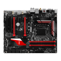
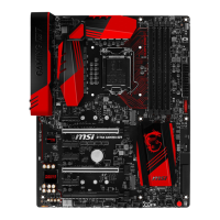
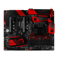
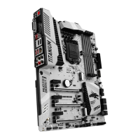
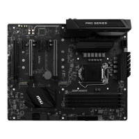
MSI Z170A SLI PLUS Specifications

General IconGeneral
ChipsetIntel Z170
CPU SocketLGA 1151
Memory Slots4 x DDR4
Maximum Memory64 GB
Form FactorATX
Storage Interface6 x SATA 6Gb/s, 1 x M.2
LANIntel I219-V Gigabit LAN
RAID SupportRAID 0, 1, 5, 10
USB Ports6 x USB 3.1 Gen1, 6 x USB 2.0
AudioRealtek ALC892
Memory SpeedDDR4 2133 MHz
Multi-GPU SupportNVIDIA 2-Way SLI, AMD 3-Way CrossFireX

Related product manuals