Ignition System
95
Adjusting the brake assembly (if equipped)
1. Disconnect and ground the spark plug wire.
2. Remove the recoil assembly and blower housing by
following the steps described in Chapter 6: Starter.
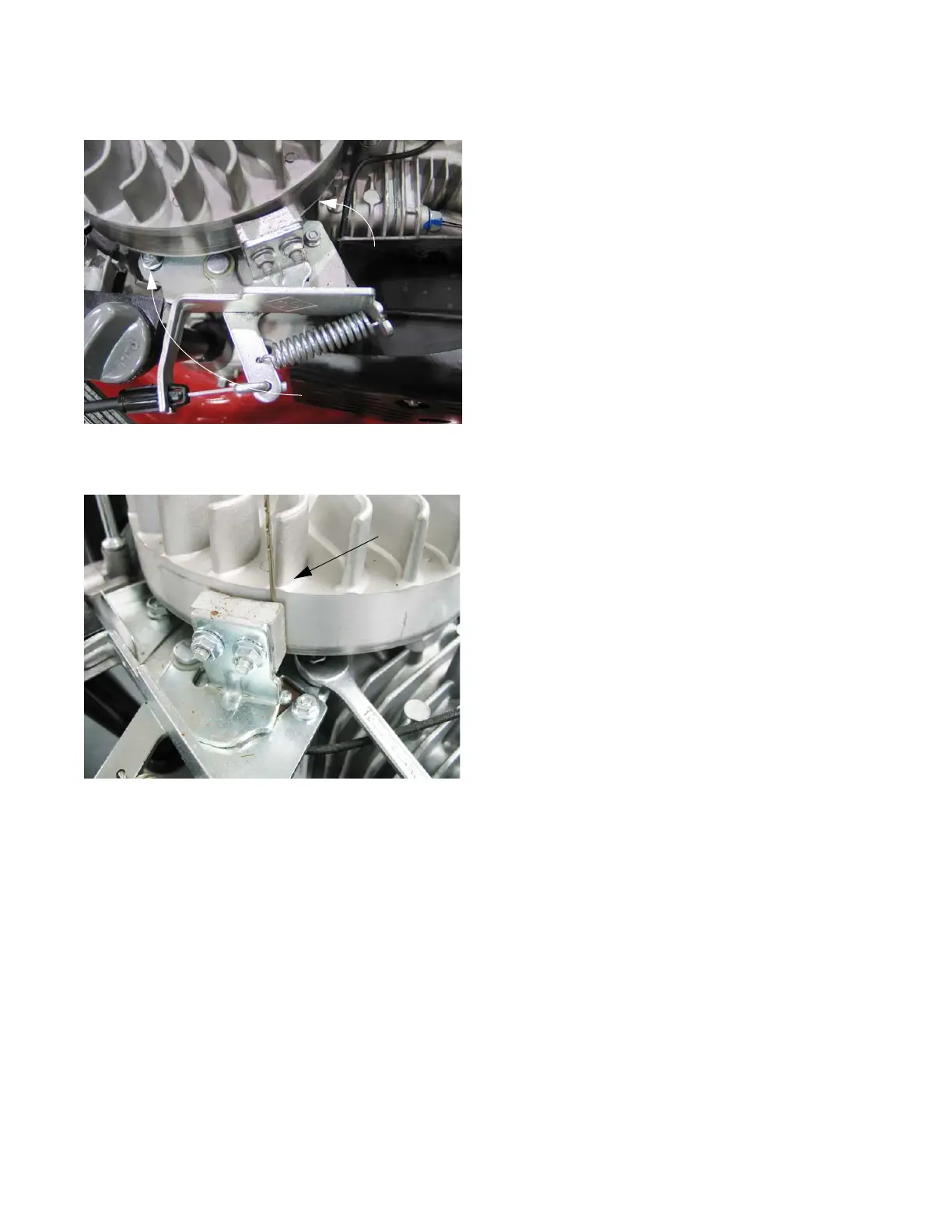
3. Slightly loosen the two bolts that holds the brake
assembly in place using a 10mm wrench.
NOTE: The bolt near the cylinder is a pivot point and the
bolt by the dip stick is in a slot. See Figure 7.20.
4. Use a spring clamp to hold the safety bail against the
upper handle bar.
5. Position the brake assembly so that the edge of the
brake pad that is nearest the slotted hole is roughly
0.050” (1.27mm) from the flywheel, then tighten the
screws. See Figure 7.21.
NOTE: The shank of an unused drill bit may be used as a
feeler gauge
6. Tighten the two bolts that hold the brake assembly in
place.
Figure 7.20
Screw:
pivot point
Screw:
Adjustment
Figure 7.21
Drill bit used
for gauge
 Loading...