FUEL SYSTEM AND GOVERNOR
61
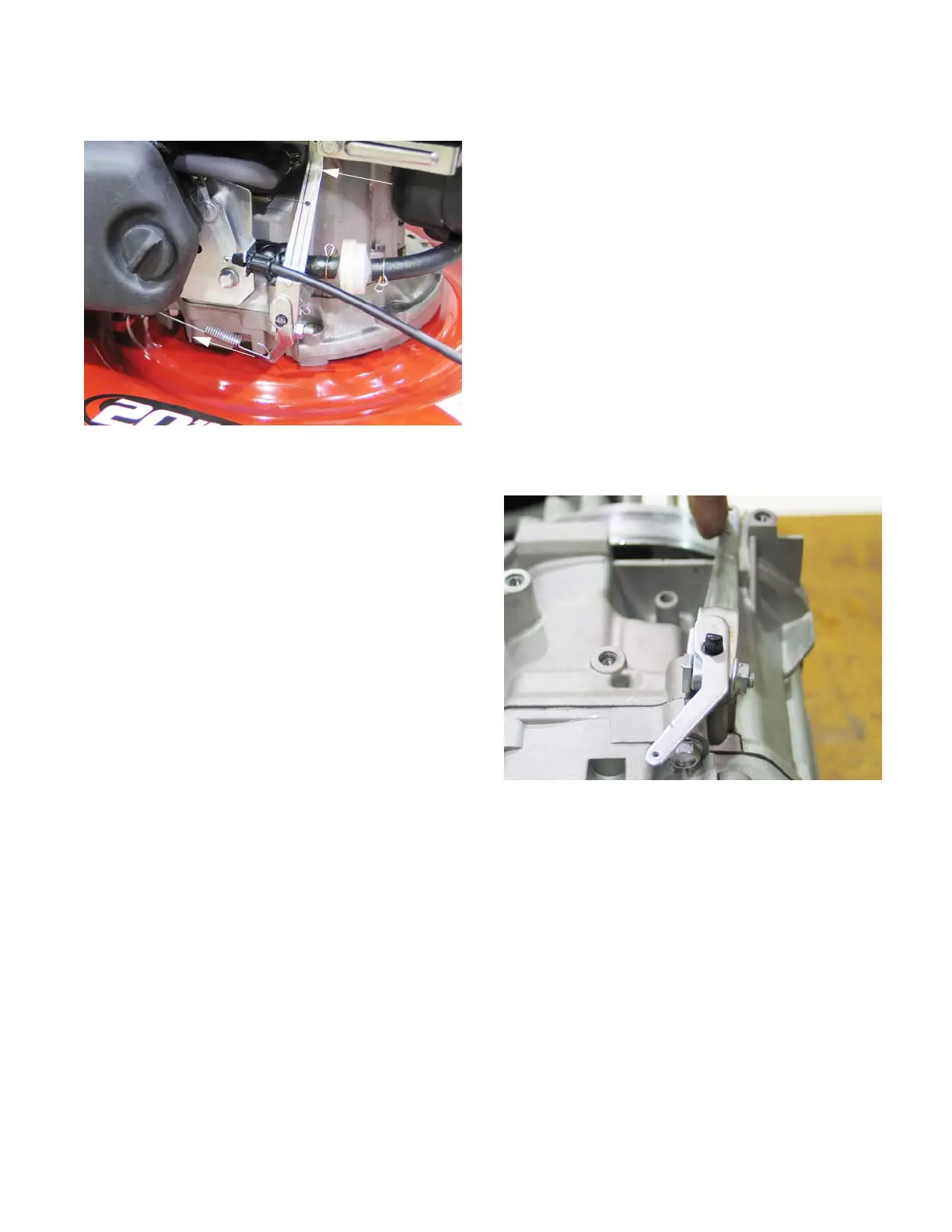
Governor
The engine speed is controlled by a balance between
the force applied by a spring (pulling the throttle open) and
a flyweight mechanism within the engine applying force to
the governor arm (pushing the throttle closed). See Figure
4.58.
NOTE: While the mechanism is simple and robust, it is
important to pay attention when working on parts
near the governor. Binding caused by interference
with mis-routed lines or cables may make the gov-
ernor unresponsive.
NOTE: When a governed engine “hunts”, it is generally an
indication of a lean fuel/air mixture, rather than a
problem with the governor.
Governor arm
1. To remove the governor arm from the governor
shaft:
1a. Unhook the governor spring.
1b. Unhook the governor linkage.
1c. Loosen the nut and through bolt. See Figure
4.59.
NOTE: The governor shaft is splined. If it is neces-
sary to remove the governor arm, make an
index mark to orient the shaft to the arm on
installation, remove the arm and go to step
3.
1d. Carefully slide the Governor arm off of the
governor shaft.
2. If the governor arm is being installed without benefit
of index marks:
2a. Rotate the governor shaft clockwise as far as it will go.
2b. Position the arm so that the throttle plate in the carburetor is at the wide open position.
3. Slide the arm onto the shaft. The flat on the top of the shaft should be roughly perpendicular to the shaft.
NOTE: There is a hairpin clip that keeps the governor shaft from sliding into the engine. It may be necessary to
hold the shaft while sliding the arm on to prevent it from going into the engine.
4. Tighten the nut on the clamp bolt to secure the arm.
NOTE: Make sure to take the slack out of the system while tightening the clamp bolt.
5. Attach the govern linkage and spring.
6. Start the engine and check the top no load RPM using a tachometer.
7. Adjust the governor to maintain top no-load speed as described in a previous section of this chapter.
Figure 4.58
Spring tension
Governor action
 Loading...