© National Instruments | 7-25
M Series User Manual
Routing a Signal to Counter n Source
Each counter has independent input selectors for the Counter n Source signal. Any of the
following signals can be routed to the Counter n Source input:
•80MHz Timebase
•20MHz Timebase
• 100 kHz Timebase
• RTSI <0..7>
• PFI <0..15>
• PXI_CLK10
• PXI_STAR
• Analog Comparison Event
In addition, Counter 1 TC or Counter 1 Gate can be routed to Counter 0 Source. Counter 0 TC
or Counter 0 Gate can be routed to Counter 1 Source.
Some of these options may not be available in some driver software.
Routing Counter n Source to an Output Terminal
You can route Counter n Source out to any PFI <0..15> or RTSI <0..7> terminal. All PFIs are
set to high-impedance at startup.
Counter n Gate Signal
The Counter n Gate signal can perform many different operations depending on the application
including starting and stopping the counter, and saving the counter contents.
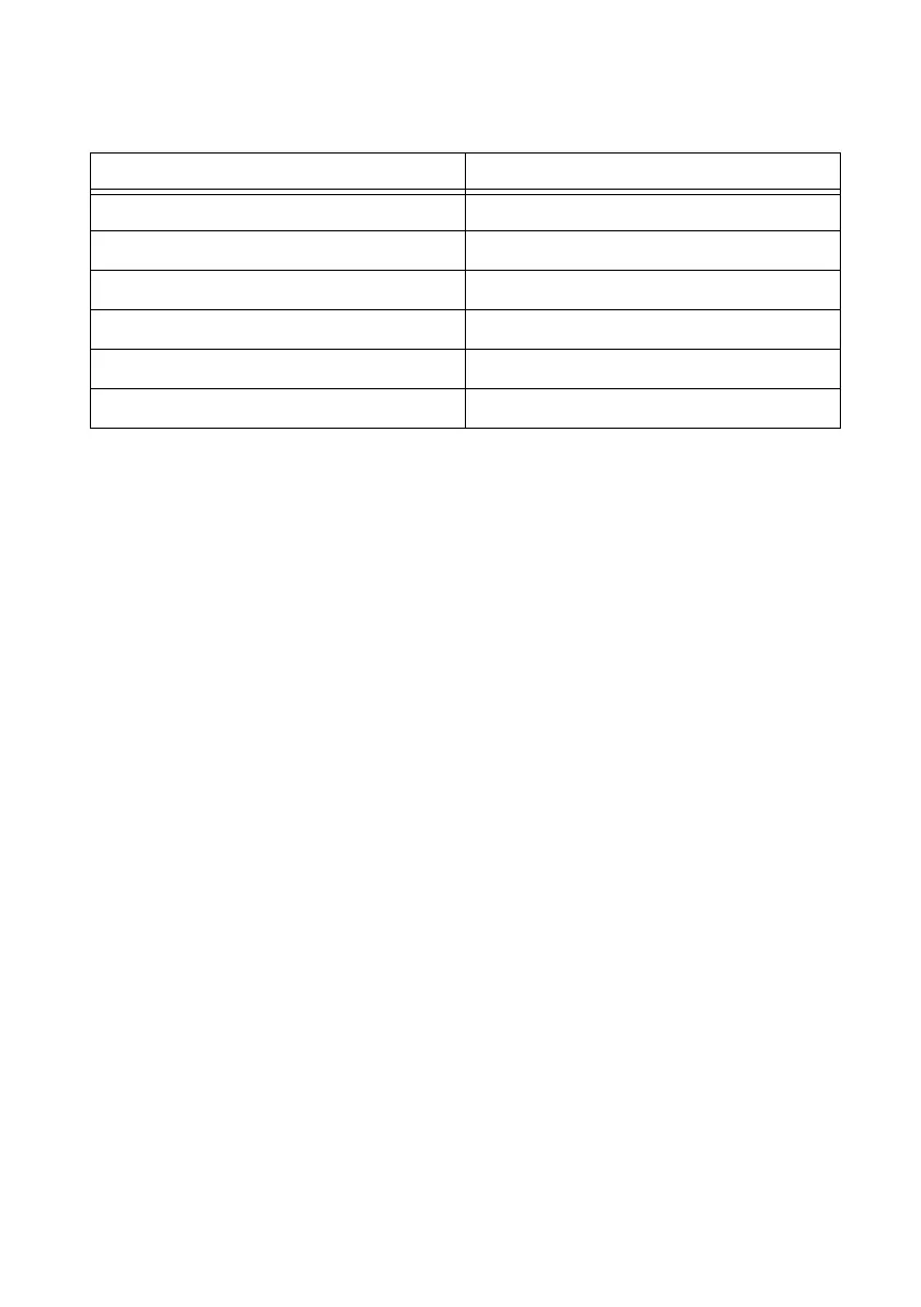
Table 7-5. Counter Applications and Counter n Source
Application Purpose of Source Terminal
Pulse Generation Counter Timebase
One Counter Time Measurements Counter Timebase
Two Counter Time Measurements Input Terminal
Non-Buffered Edge Counting Input Terminal
Buffered Edge Counting Input Terminal
Two-Edge Separation Counter Timebase

 Loading...


