© National Instruments | 9-5
M Series User Manual
Using RTSI as Outputs
RTSI <0..7> are bidirectional terminals. As an output, you can drive any of the following signals
to any RTSI terminal:
• AI Start Trigger (ai/StartTrigger)
• AI Reference Trigger (ai/ReferenceTrigger)
• AI Convert Clock* (ai/ConvertClock)
• AI Sample Clock (ai/SampleClock)
• AI Pause Trigger (ai/PauseTrigger)
• AO Sample Clock* (ao/SampleClock)
• AO Start Trigger (ao/StartTrigger)
• AO Pause Trigger (ao/PauseTrigger)
• 10 MHz Reference Clock
• Counter n Source, Gate, Z, Internal Output
• Change Detection Event
• Analog Comparison Event
• FREQ OUT
• PFI <0..5>
Note Signals with a * are inverted before being driven on the RTSI terminals.
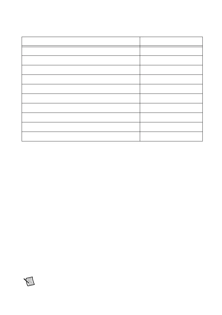
Table 9-1. RTSI Signals
RTSI Bus Signal Terminal
RTSI 7 34
RTSI 6 32
RTSI 5 30
RTSI 4 28
RTSI 3 26
RTSI 2 24
RTSI 1 22
RTSI 0 20
Not Connected. Do not connect signals to these terminals. 1 to 18
D GND 19, 21, 23, 25, 27, 29, 31, 33

 Loading...


