5-6 | ni.com
Chapter 5 Analog Output
Analog Output Timing Signals
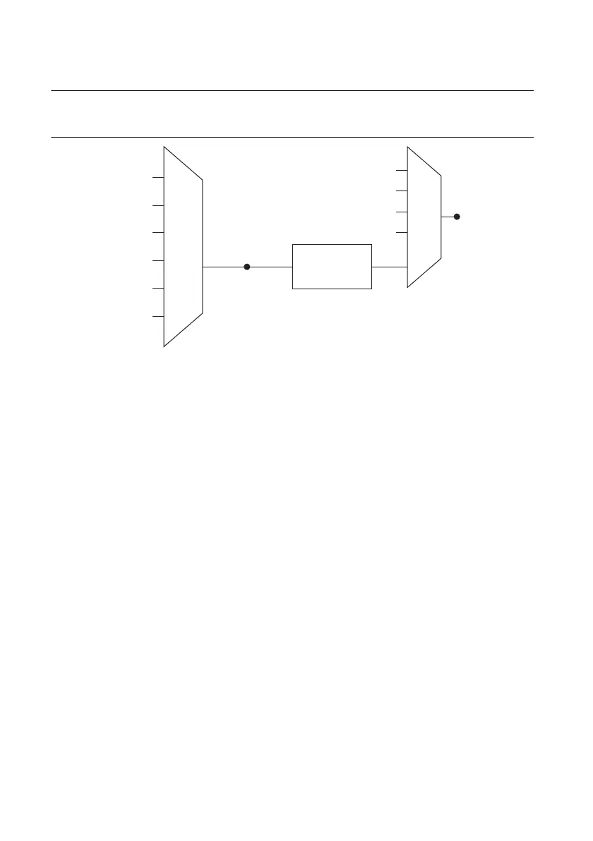
Figure 5-3 summarizes all of the timing options provided by the analog output timing engine.
Figure 5-3. Analog Output Timing Options
M Series devices feature the following AO (waveform generation) timing signals:
• AO Start Trigger Signal
• AO Pause Trigger Signal
• AO Sample Clock Signal
• AO Sample Clock Timebase Signal
AO Start Trigger Signal
Use the AO Start Trigger (ao/StartTrigger) signal to initiate a waveform generation. If you do
not use triggers, you can begin a generation with a software command.
Using a Digital Source
To use AO Start Trigger, specify a source and an edge. The source can be one of the following
signals:
• A pulse initiated by host software
• PFI <0..15>
• RTSI <0..7>
• AI Reference Trigger (ai/ReferenceTrigger)
• AI Start Trigger (ai/StartTrigger)
• PXI_STAR
The source also can be one of several internal signals on your DAQ device. Refer to Device
Routing in MAX in the NI-DAQmx Help or the LabVIEW Help for more information.
PFI, RTSI
PXI_STA R
Analog Comparison
Event
20 MHz Timebase
100 kHz Timebase
PXI_CLK10
Programmable
Clock
Divider
AO Sample Clock
Timebase
PFI, RTSI
PXI_STA R
Analog Comparison Event
Ctr n Internal Output
AO Sample Clock

 Loading...


