11-2 | ni.com
Chapter 11 Triggering
Triggering with an Analog Source
Some M Series devices can generate a trigger on an analog signal. To find your device triggering
options, refer to the specifications document for your device.
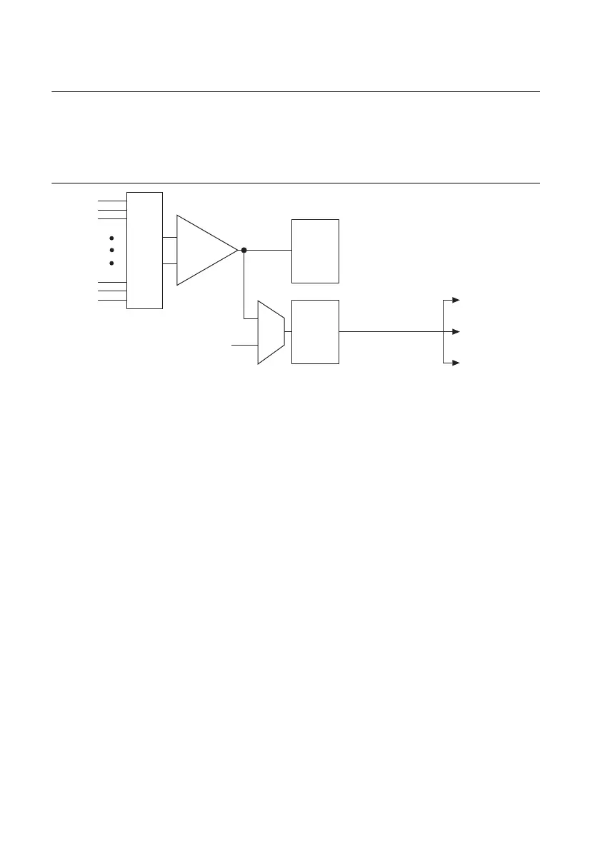
Figure 11-2 shows the analog trigger circuit.
Figure 11-2. Analog Trigger Circuit
You must specify a source and an analog trigger type. The source can be either an APFI <0,1>
terminal or an analog input channel.
APFI <0,1> Terminals
When you use either APFI <0,1> terminal as an analog trigger, you should drive the terminal
with a low impedance signal source (less than 1 kΩ source impedance). If APFI <0,1> are left
unconnected, they are susceptible to crosstalk from adjacent terminals, which can cause false
triggering. Note that the APFI <0,1> terminals also can be used for other functions such as the
AO External Reference input, as described in the AO Offset and AO Reference Selection section
of Chapter 5, Analog Output.
Analog Input Channels
Select any analog input channel to drive the NI-PGIA. The NI-PGIA amplifies the signal as
determined by the input ground-reference setting and the input range. The output of the NI-PGIA
then drives the analog trigger detection circuit. By using the NI-PGIA, you can trigger on very
small voltage changes in the input signal.
When the DAQ device is waiting for an analog trigger with a AI channel as the source, the AI
muxes should not route different AI channels to the NI-PGIA. If a different channel is routed to
the NI-PGIA, the trigger condition on the desired channel could be missed. The other channels
also could generate false triggers.
Analog
Input
Channels
PGIA
–
+
ADC
Mux
Analog
Trigger
Detection
Analog Comparison
Event
(Analog Trigger
Circuitry Output)
APFI <0,1>
AI Circuitry
AO Circuitry
Counter Circuitry

 Loading...


