© National Instruments | 3-7
M Series User Manual
RTSI Connector Pinout
(PCI/PCIe-622x/625x/628x Devices) Refer to the RTSI Connector Pinout section of
Chapter 9, Digital Routing and Clock Generation, for information about the RTSI connector.
LED Patterns
(USB-622x/625x/628x Devices) All variants of M Series USB devices have LEDs labeled
ACTIVE and READY. The ACTIVE LED indicates activity over the bus. The READY LED
indicates whether or not the device is configured. Table 3-2 shows the behavior of the LEDs.
Note USB-62xx BNC devices also have a POWER (+5 V) LED on the top panel.
The POWER (+5 V) LED indicates device power.
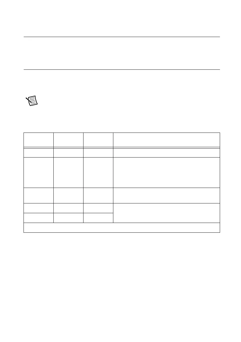
Table 3-2. LED Patterns
POWER
(+5 V) LED
*
ACTIVE
LED
READY
LED USB Device State
Off Off Off The device is not powered.
On Off Off (USB-62xx Screw Terminal/Mass Termination
Devices) The device is not powered.
(USB-62xx BNC Devices) The device is powered
but not connected to the host computer.
On Off On The device is configured, but there is no activity over
the bus.
On On On The device is configured and there is activity over the
bus.
On Blinking On
*
USB-625x/628x BNC devices only.

 Loading...


