© National Instruments | 2-1
2
DAQ System Overview
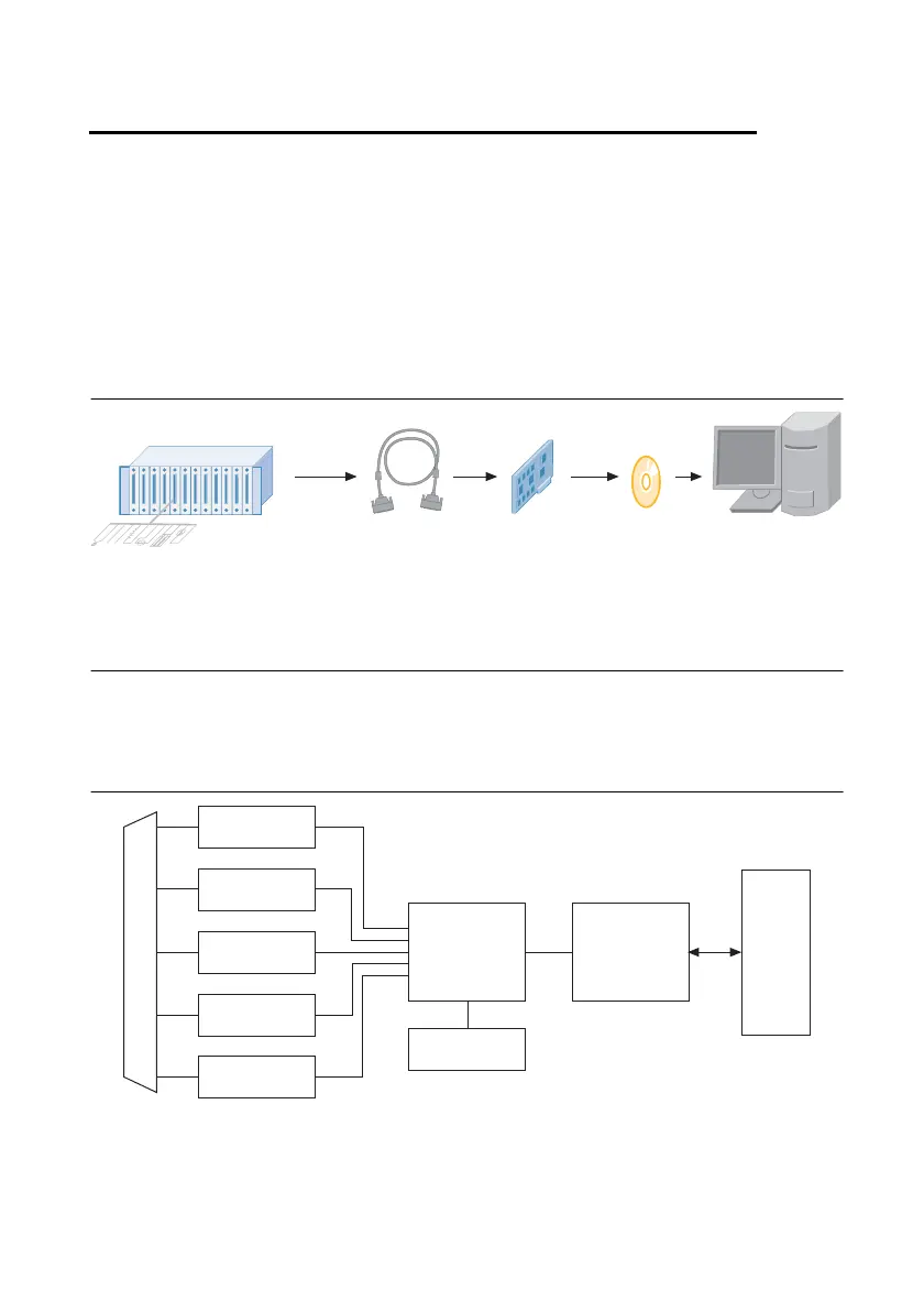
Figure 2-1 shows a typical DAQ system, which includes sensors, transducers, signal
conditioning devices, cables that connect the various devices to the accessories, the M Series
device, programming software, and PC. The following sections cover the components of a
typical DAQ system.
Figure 2-1. Components of a Typical DAQ System
DAQ Hardware
DAQ hardware digitizes signals, performs D/A conversions to generate analog output signals,
and measures and controls digital I/O signals. Figure 2-2 features components common to all
M Series devices.
Figure 2-2. General M Series Block Diagram
Sensors and
Transducers
Signal
Conditioning
DAQ
Hardware
Personal Computer
or
PXI/PXI Express
Chassis
DAQ
Software
Cables and
Accessories
Analog Output
Digital I/O
Analog Input
Counters
PFI
Digital
Routing
and Clock
Generation
Bus
Interface
Bus
I/O Connector
RTSI

 Loading...


