A-24 | ni.com
Appendix A Module/Device-Specific Information
Note For a detailed description of each signal, refer to the I/O Connector Signal
Descriptions section of Chapter 3, Connector and LED Information.
Note For more information about default NI-DAQmx counter inputs, refer to
Connecting Counter Signals in the NI-DAQmx Help or the LabVIEW Help.
USB-6229 Screw Terminal Important Links
The following list contains links specific to your DAQ device:
• Specifications—Refer to the NI 6229 Specifications for more detailed information about
the USB-6229 Screw Terminal device.
• LED Patterns—Refer to the LED Patterns section of Chapter 3, Connector and LED
Information, for information about the USB-6229 Screw Terminal LEDs.
• Fuse Replacement—Refer to the USB Device Fuse Replacement section of Chapter 1,
Getting Started, for information about replacing the fuse on the USB-6229 Screw Terminal.
• Accessory Options—Refer to the USB Device Accessories, USB Cable, and Power Supply
section of Chapter 2, DAQ System Overview, for more information.
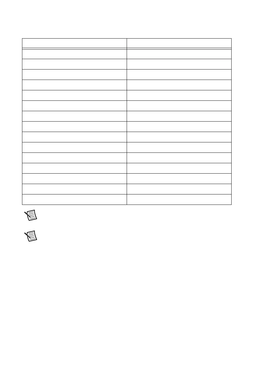
Table A-11. Default NI-DAQmx Counter/Timer Pins
Counter/Timer Signal Default Pin Number (Name)
CTR 0 SRC 81 (PFI 8)
CTR 0 GATE 83 (PFI 9)
CTR 0 AUX 85 (PFI 10)
CTR 0 OUT 89 (PFI 12)
CTR 0 A 81 (PFI 8)
CTR 0 Z 83 (PFI 9)
CTR 0 B 85 (PFI 10)
CTR 1 SRC 76 (PFI 3)
CTR 1 GATE 77 (PFI 4)
CTR 1 AUX 87 (PFI 11)
CTR 1 OUT 91 (PFI 13)
CTR 1 A 76 (PFI 3)
CTR 1 Z 77 (PFI 4)
CTR 1 B 87 (PFI 11)
FREQ OUT 93 (PFI 14)

 Loading...


