© National Instruments | 6-19
X Series User Manual
Note When using your X Series device to control an SCXI chassis, DIO lines 0, 1,
2, and 4 are used as communication lines and must be left to power-up in the default
high-impedance state to avoid potential damage to these signals.
DI Change Detection
You can configure the DAQ device to detect changes on all 32 digital input lines (P0, P1, and
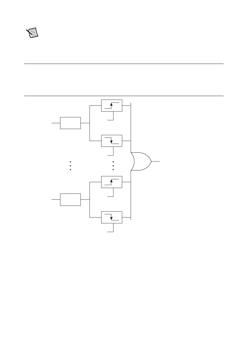
P2) and all 16 PFI lines. Figure 6-11 shows a block diagram of the DIO change detection
circuitry.
Figure 6-11. DI Change Detection
You can enable the DIO change detection circuitry to detect rising edges, falling edges, or either
edge individually on each DIO line. The DAQ devices synchronize each DI signal to the
100 MHz Timebase, and then sends the signal to the change detectors. The circuitry ORs the
output of all enabled change detectors from every DI signal. The result of this OR is the Change
Detection Event signal.
Change detection performs bus correlation by considering all changes within a 50 ns window
one change detection event, which keeps signals on the same bus synchronized in samples and
prevents overruns.
Synch
Synch
P0.0
P2.7
Enable
Enable
Enable
Enable
Change Detection Event

 Loading...