4-22 | ni.com
Chapter 4 Analog Input
Analog Input Timing Signals
In order to provide all of the timing functionality described throughout this section, MIO
X Series devices have a flexible timing engine. Figure 4-12 summarizes all of the timing options
provided by the analog input timing engine. Also refer to the
Clock Routing section of Chapter 9,
Digital Routing and Clock Generation.
Figure 4-12. Analog Input Timing Options
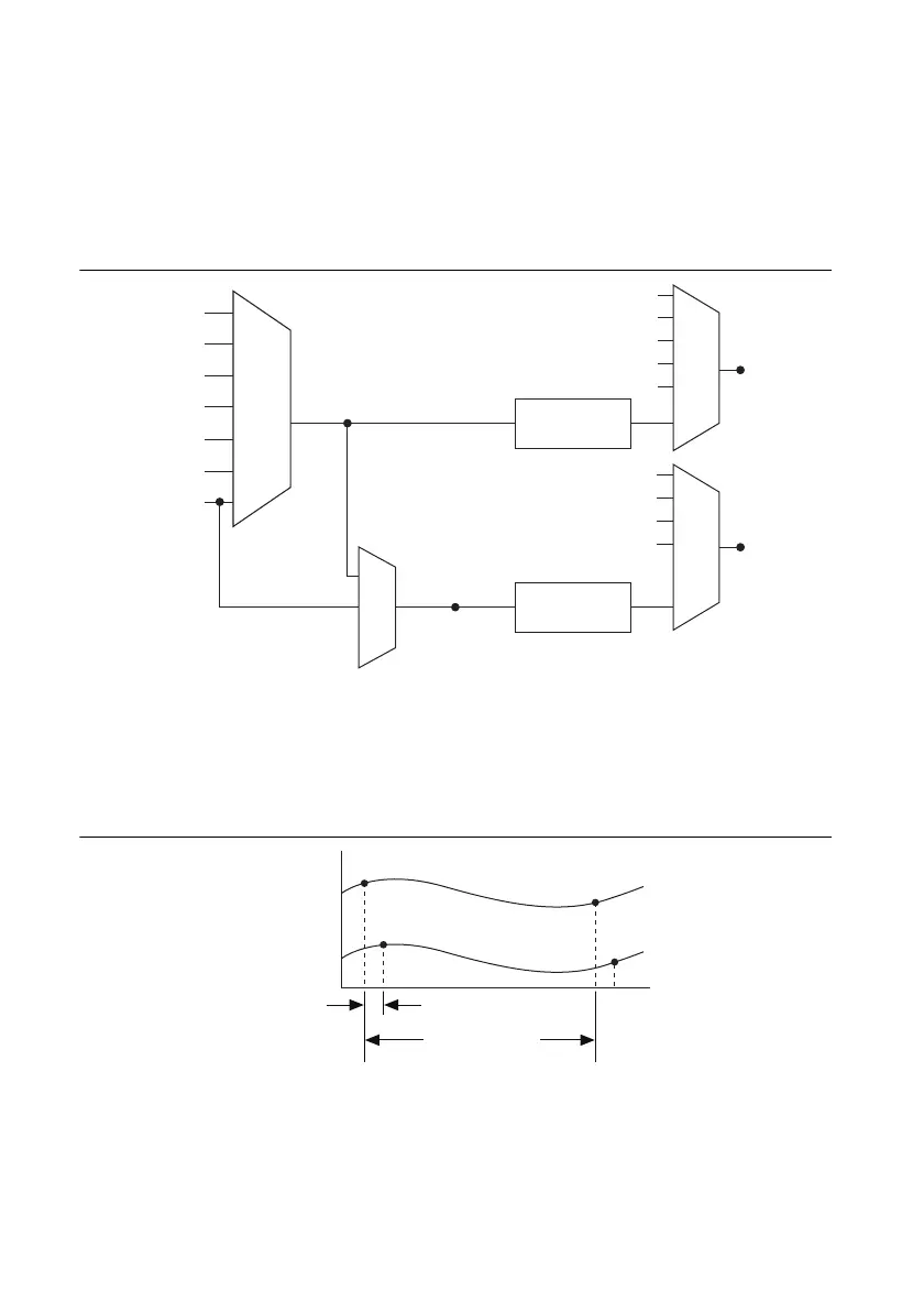
MIO X Series devices use AI Sample Clock (ai/SampleClock) and AI Convert Clock
(ai/ConvertClock) to perform interval sampling. As Figure 4-13 shows, AI Sample Clock
controls the sample period, which is determined by the following equation:
1/Sample Period = Sample Rate
Figure 4-13. MIO X Series Interval Sampling
AI Convert Clock controls the Convert Period, which is determined by the following equation:
1/Convert Period = Convert Rate
PFI, RTSI
PXI_STA R
Analog Comparison
Event
20 MHz Timebase
100 kHz Timebase
PXI_CLK10
Programmable
Clock
Divider
Programmable
Clock
Divider
AI Sample Clock
Timebase
AI Convert Clock
Timebase
PFI, RTSI
PXI_STA R
Analog Comparison Event
Ctr
n Internal Output
SW Pulse
PFI, RTSI
PXI_STA R
Analog Comparison Event
Ctr
n Internal Output
AI Convert Clock
AI Sample Clock
100 MHz Timebase
Channel 0
Channel 1
Convert Period
Sample Period

 Loading...