Chapter 11 Triggering
M Series User Manual 11-2 ni.com
You also can program your DAQ device to perform an action in response to
a trigger from a digital source. The action can affect the following:
• Analog input acquisition
• Analog output generation
• Counter behavior
• Digital waveform acquisition and generation
Triggering with an Analog Source
Some M Series devices can generate a trigger on an analog signal. To find
your device triggering options, refer to the specifications document for
your device.
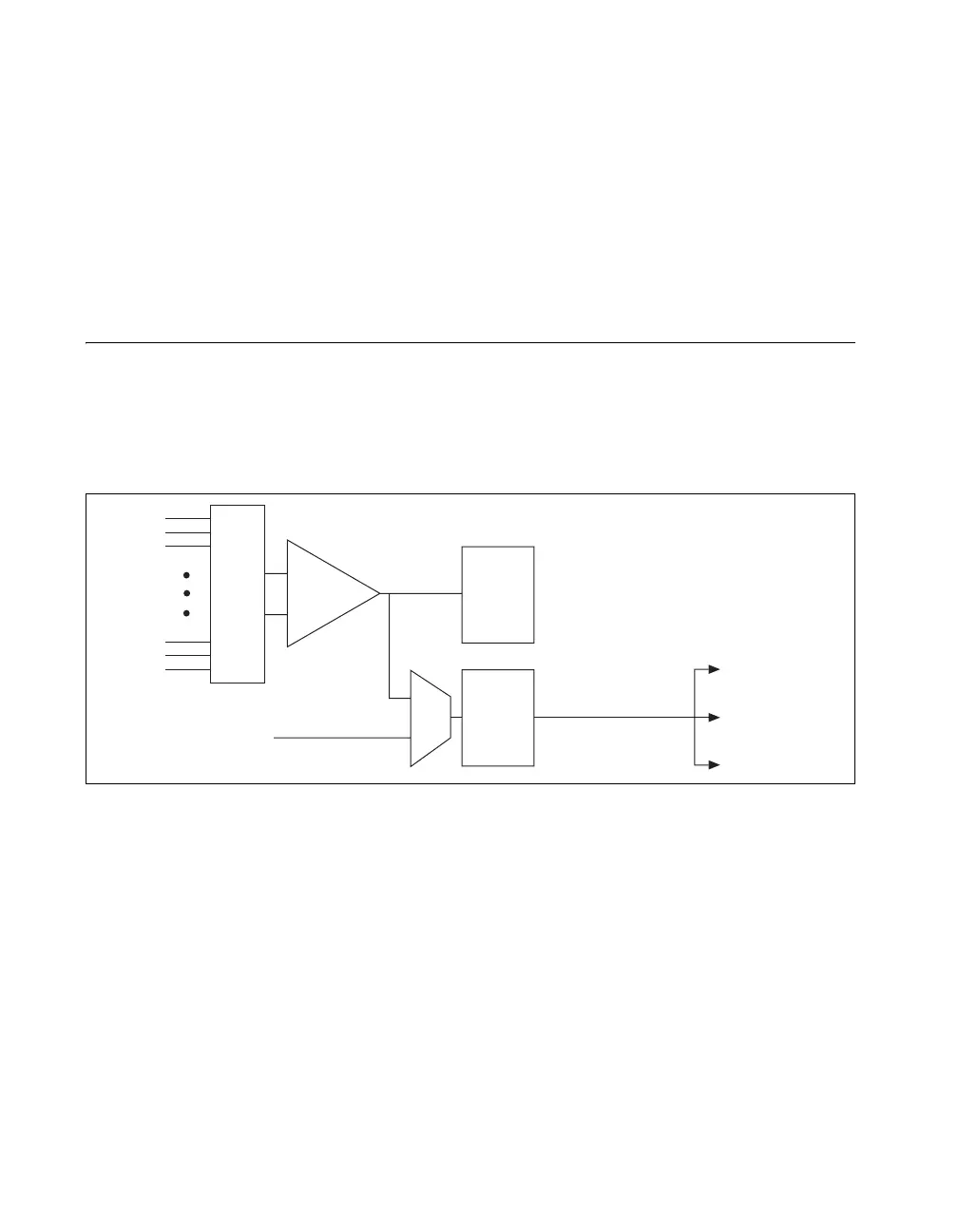
Figure 11-2 shows the analog trigger circuit.
Figure 11-2. Analog Trigger Circuit
You must specify a source and an analog trigger type. The source can be
either an APFI <0..1> terminal or an analog input channel.
APFI <0..1> Terminals
When you use either APFI <0..1> terminal as an analog trigger, you should
drive the terminal with a low-impedance signal source (less than 1 kΩ
source impedance). If APFI <0..1> are left unconnected, they are
susceptible to crosstalk from adjacent terminals, which can cause false
triggering. Note that the APFI <0..1> terminals also can be used for other
functions such as the AO External Reference input, as described in the AO
Offset and AO Reference Selection section of Chapter 5, Analog Output.
Analog
Input
Channels
PGIA
–
+
ADC
Mux
Analog
Trigger
Detection
Analog Comparison
Event
(Analog Trigger
Circuitry Output)
APFI <0..1>
AI Circuitry
AO Circuitry
Counter Circuitr
 Loading...