Chapter 6 Digital I/O
X Series User Manual 6-18 ni.com
Routing DO Sample Clock to an Output Terminal
You can route DO Sample Clock (as an active low signal) out to any
PFI <0..15>, RTSI <0..7>, or PXIe-DSTARC terminal.
Other Timing Requirements
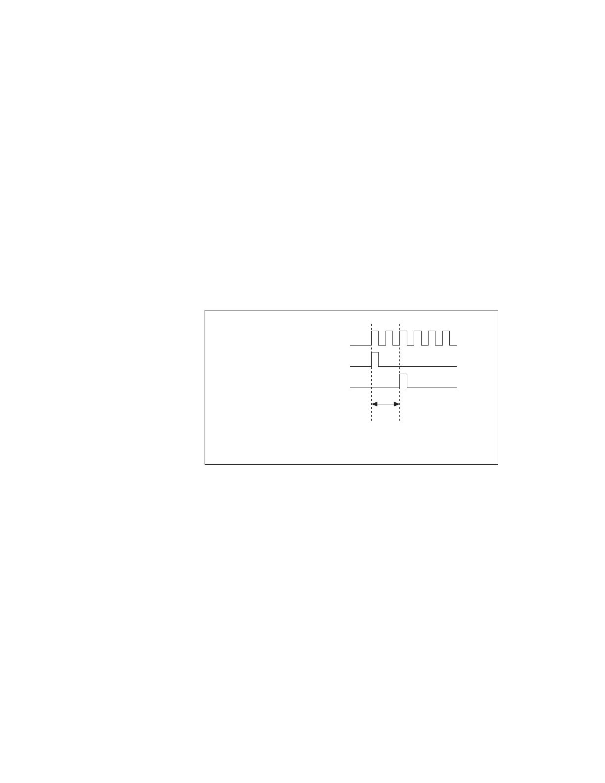
The DO timing engine on your device internally generates DO Sample
Clock unless you select some external source. DO Start Trigger starts the
timing engine and either the software or hardware can stop it once a finite
generation completes. When using the DO timing engine, you also can
specify a configurable delay from DO Start Trigger to the first DO Sample
Clock pulse. By default, this delay is two ticks of DO Sample Clock
Timebase. Figure 6-7 shows the relationship of DO Sample Clock to DO
Start Trigger.
Figure 6-7. DO Sample Clock and DO Start Trigger
DO Sample Clock Timebase Signal
The DO Sample Clock Timebase (do/SampleClockTimebase) signal is
divided down to provide a source for DO Sample Clock. You can route any
of the following signals to be the DO Sample Clock Timebase signal:
• 100 MHz Timebase (default)
• 20 MHz Timebase
• 100 kHz Timebase
•PXI_CLK10
• PFI <0..15>
•RTSI <0..7>
DO Sample Clock Timebase
DO Start Trigger
DO Sample Clock
Delay
From
Start
Trigger
Artisan Technology Group - Quality Instrumentation ... Guaranteed | (888) 88-SOURCE | www.artisantg.com
 Loading...


