Chapter 4 Analog Input
© National Instruments 4-49 X Series User Manual
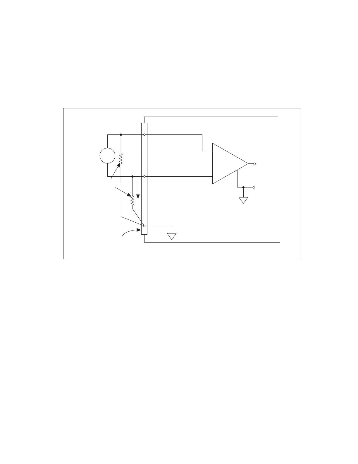
Differential Connections for Floating Signal Sources
Figure 4-27 shows how to connect a floating (or non-referenced) signal
source to a channel on an Simultaneous MIO X Series device.
Figure 4-27. Differential Connection for Floating Signals on Simultaneous MIO
X Series Devices
Figure 4-27 shows bias resistors connected between AI 0–, AI 0+, and the
floating signal source grou nd. These resistors provide a return path for the
bias current. A value of 10 kΩ to 100 kΩ is usually sufficient. If you do not
use the resistors and the source is truly floating, the source is not likely to
remain within the common-mode signal range of the instrumentation
amplifier, so the instrumentation amplifier saturates, causing erroneous
readings. You must reference the source to the respective channel ground.
+
+
Floating
Signal
Source
Instrumentation
Amplifier
V
m
Measured
Voltage
I/O Connector
AI 0 GND
Bias
Current
Return
Paths
AI 0 –
AI 0 +
AI 0 Connections Shown
Bias
Resistors
–
+
–
–
Simultaneous X Series Device
V
s
Artisan Technology Group - Quality Instrumentation ... Guaranteed | (888) 88-SOURCE | www.artisantg.com
 Loading...


