Chapter 6 Digital I/O
© National Instruments 6-29 X Series User Manual
You can set the watchdog timer timeout period to specify the amount of
time that mu st elapse before the watchdog timer expires. The counter on the
watchdog timer is configurable up to (2
32
– 1) × 8 ns (approximately
34 seconds) before it expires. A watchdog timer can be set for all DIO and
PFI lines.
Connecting Digital I/O Signals
The DIO signals, P0.<0..31>, P1.<0..7>, and P2.<0..7> are referenced to
D GND. You can individually program each line as an input or output.
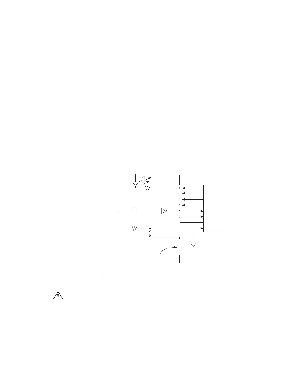
Figure 6-16 shows P1.<0..3> configured for digital input and P1.<4..7>
configured for digital output. Digital input applications include receiving
TTL signals and sensing external device states, such as the state of the
switch shown in the figure. Digital output applications include sending
TTL signals and driving external devices, such as the LED shown in
Figure 6-16.
Figure 6-16. Digital I/O Connections
Caution
Exceeding the maximum input voltage ratings, which are listed in the
specifications document for each X Series device, can damage the DAQ device and the
computer. NI is not liable for any damage resulting from such signal connections.
+5 V
LED
TTL Signal
+5 V
Switch
I/O Connector
D GND
X Series Device
P1.<0..3>
P1.<4..7>
Artisan Technology Group - Quality Instrumentation ... Guaranteed | (888) 88-SOURCE | www.artisantg.com
 Loading...


