Chapter 3 Connector and LED Information
© National Instruments 3-3 X Series User Manual
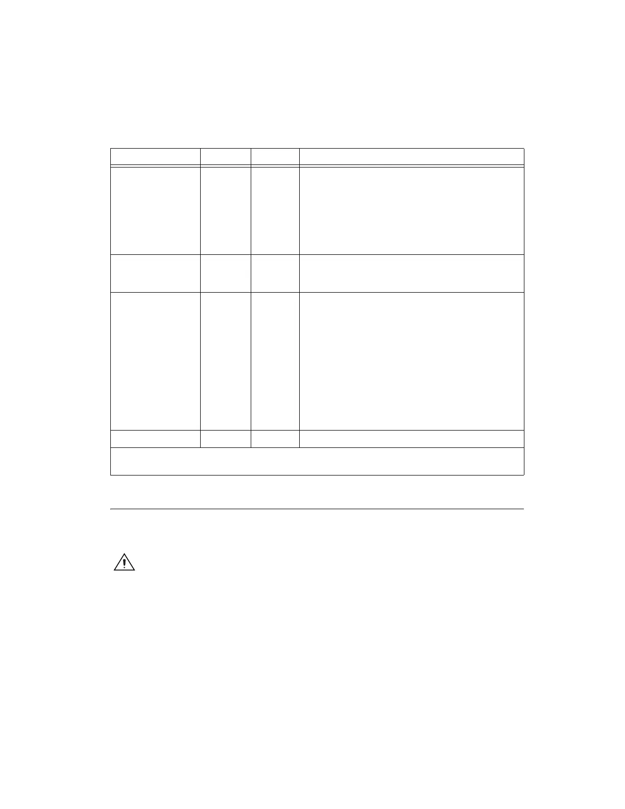
+5 V Power Source
The +5 V terminals on the I/O connector supply +5 V referenced to
D GND. Use these terminals to power external circuitry.
Caution Never connect the +5 V power terminals to analog or digital ground or to any
other voltage source on the X Series device or any other device. Doing so can damage the
device and the computer. NI is not liable for damage resulting from such a connection.
The power rating on most devices is +4.75 VDC to +5.25 VDC at 1 A.
Refer to the specifications document for your device to obtain the device
power rating.
APFI <0,1> AO GND
or AI GND
Input Analog Programmable Function Interface Channels
0to1—Each APFI signal can be used as AO external reference
inputs for AO <0..3>, or as an analog trigger input. APFI <0,1>
are referenced to AI GND when they are used as analog trigger
inputs. APFI <0,1> are referenced to AO GND when they are
used as AO external offset or reference inputs. These functions are
not available on all devices. Refer to the specifications for your
device.
+5 V D GND Output +5 V Power Source—These terminals provide a fused +5 V
power source. Refer to the +5 V Power Source section for more
information.
PFI <0..7>/P1.<0..7>
PFI <8..15>/P2.<0..7>
D GND Input or
Output
Programmable Function Interface or Digital I/O Channels 0
to 7 and Channels 8 to 15—Each of these terminals can be
individually configured as a PFI terminal or a digital I/O terminal.
As an input, each PFI terminal can be used to supply an external
source for AI, AO, DI, and DO timing signals or counter/timer
inputs.
As a PFI output, you can route many different internal AI, AO, DI,
or DO timing signals to each PFI terminal. You also can route the
counter/timer outputs to each PFI terminal.
As a Port 1 or Port 2 digital I/O signal, you can individually
configure each signal as an input or output.
NC — — No connect—Do not connect signals to these terminals.
*
Though AI GND, AO GND, and D GND are connected on the X Series device, they are connected by small traces to reduce
crosstalk between subsystems. Each ground has a slight difference in potential.
Table 3-1. I/O Connector Signals (Continued)
Signal Name Reference Direction Description
Artisan Technology Group - Quality Instrumentation ... Guaranteed | (888) 88-SOURCE | www.artisantg.com
 Loading...


